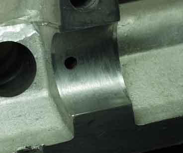
These cam bores look pretty good. You can check them with Plastigage, but I didn't see the point as fine looking at these were.
revised Feb 16, 2001
Once my engine case was clean, I checked all the critical stuff that I could to make sure I wasn't about to waste my time on this thing. Fortunately, the Corvair engine is not likely to need line-boring like the VWs often do. I carefully inspected everything for wear and damage, and checked the fit of the new lifters in the bores, the cam in its bores, and the new bearings in the their saddles.
Don't think for a second that you can just clean up the parts, put it together, and you're done. It won't happen, at least not with the 3100cc big bore. So save yourself the trouble and completely trial assembly the engine to work all the bugs out BEFORE final assembly. It'll save you time in the long run, and probably keep aluminum chips and other debris out of your engine. And don't balance your crank/rods/piston assemblies until AFTER the trial assembly, because you will probably have to clearance some piston skirts. Don't ask how I know this...
These cam bores look pretty good. You can check them with Plastigage, but I didn't see the point as fine looking at these were.
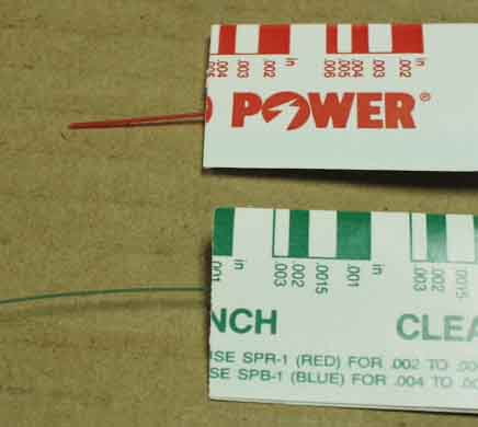
This is Plastigage. It comes in different thicknesses (ranges) and is nothing more than a plastic thread that flattens out when compressed. The wrapper comes with a scale which shows how flat it is, therefore, how much clearance you have between mating parts such as bearings.
The lifter bores looked good, and the lifters were a nice snug fit inside them.
Convinced that all was "good enough for KR", I ran a tap through all the threads from which bolts had been removed...
...and ran a die over the all of the exposed threads, restoring them and eliminating rust that might cause inaccurate torque readings at assembly time.
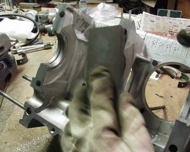
The Corvair case is full of casting flaws and flashing that nobody bothered to remove during manufacture. These are among the most hideous, and were quickly ground away with a die grinder. The case halves don't even match up, so you might as well save some weight and make them meet by cutting away the excess. (This picture was taken before case cleaning, on my other engine)
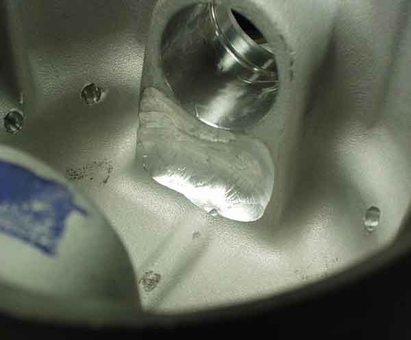
Stuff like these casting imperfections were cleaned up too. See that little blob of aluminum sitting there? It didn't come loose for 35 years, but the least I can do is get it out of my engine...
...so I did!
The case halves were lightly "stoned" with a knife sharpening stone to remove high spots...
...such as the area around this bolt hole.
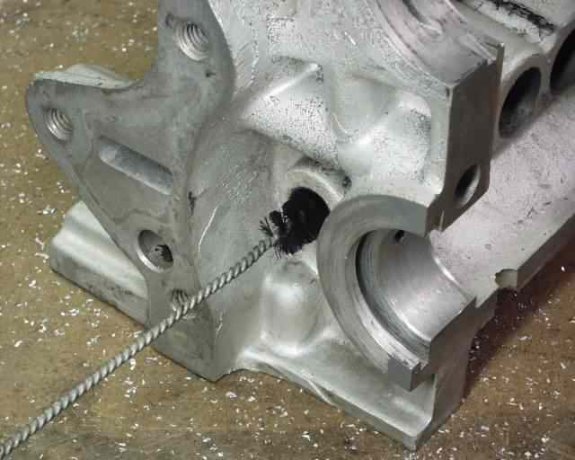
One of the last steps was to clean out this oil passage with a bottle brush and a rifle cleaning brush. Once all the case cleanup and grinding was finished, I pressure washed the case halves in a large plastic drip pan in my driveway, making a special effort to blast out the oil passages, lifter bores, etc. Of course, I eventually had to do this several times after "adjustments" to the case.
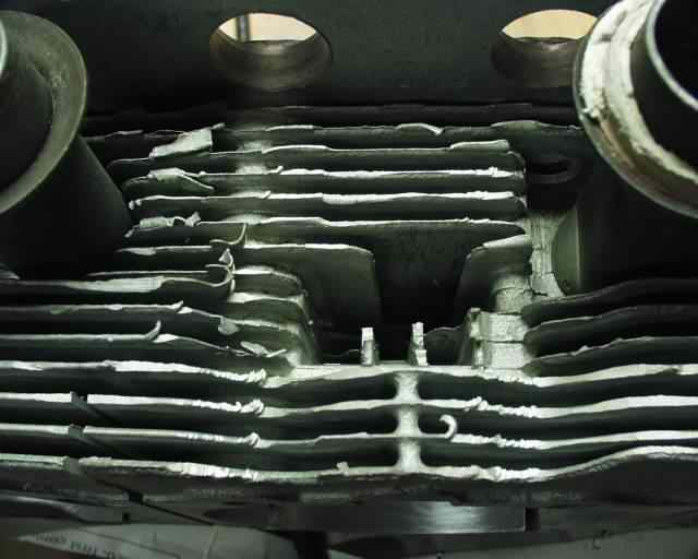
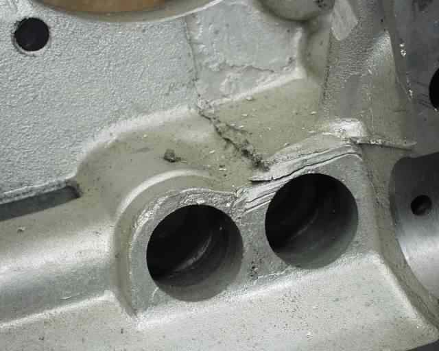
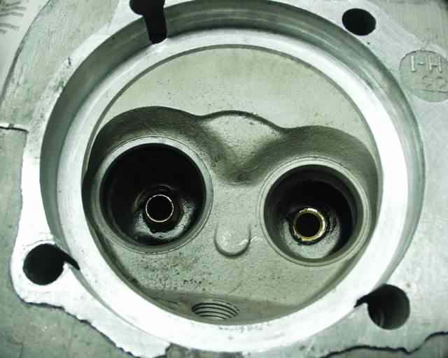
Next were the heads. This case flashing is another example of how quick GM wanted to get these heads out of the factory! This stuff doesn't help airflow one bit!
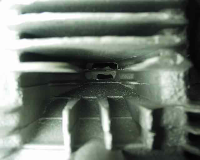
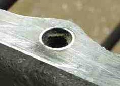
And the view down this hole doesn't look too good either. Probably 80% of the passage is blocked by casting flashing.
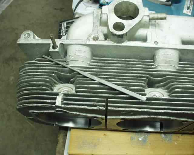
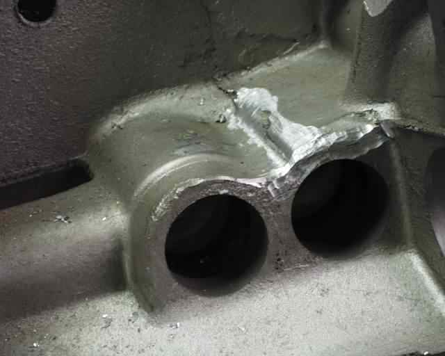
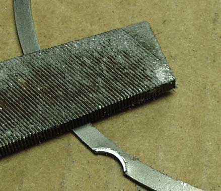
I used this file (one of a set of 6 or 7 "mini-files" that I got from Sears) to do the vast majority of the filing. Thanks to CorvAIRCRAFTer Tom Cummings for that idea! I also used a 12" long 1/8" drill bit to get a start on the really thick stuff, or to break a hole through where there was no hole yet!
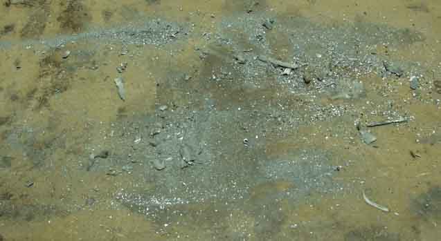
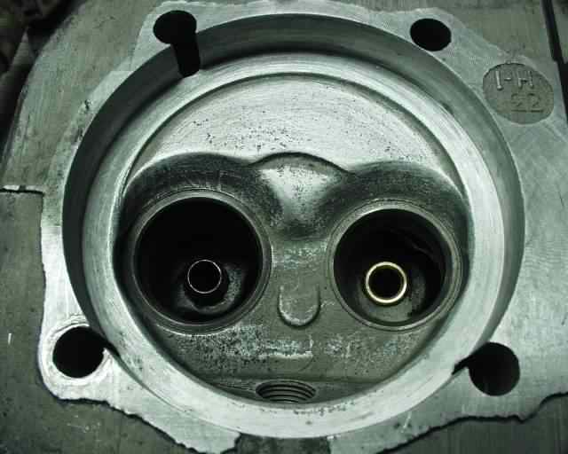
This pile of aluminum came out of one head! It took me about 2 hours per head to clean out all the flashing. The increase in cooling is quite measureable, so don't skip this critical step!
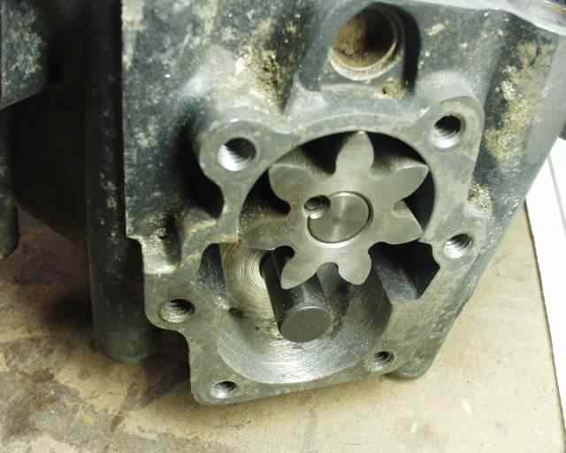
The oil pump housing needs to be checked to make sure the walls are not scored, and that the pump gear isn't rusted solid to the shaft.
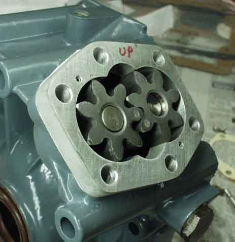
Here I added a slightly higher volume oil pump, since I will have a remotely mounted cooler and filter. The oil fitting holes need to be moved over about 3/16 in each direction away from the center, to make sure the hose fittings can be turned.
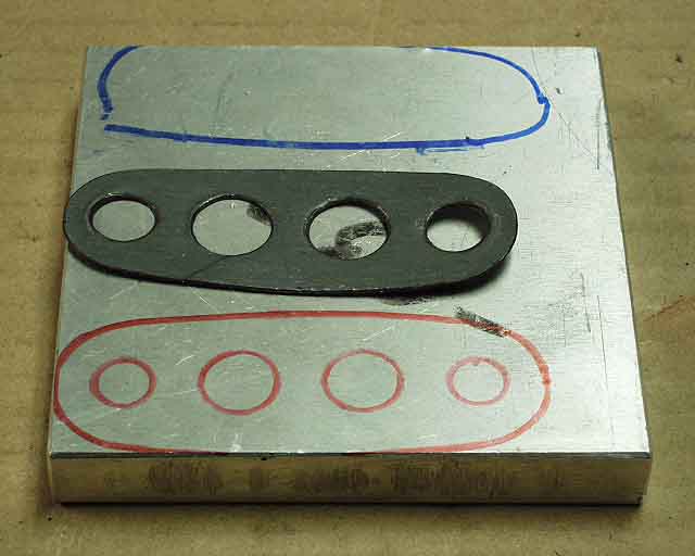
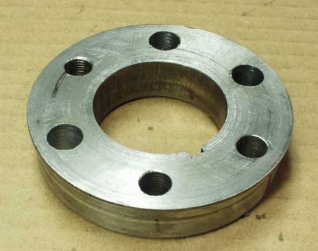
I made an adapter plate from 1/2" aluminum plate, using the gasket as a template.
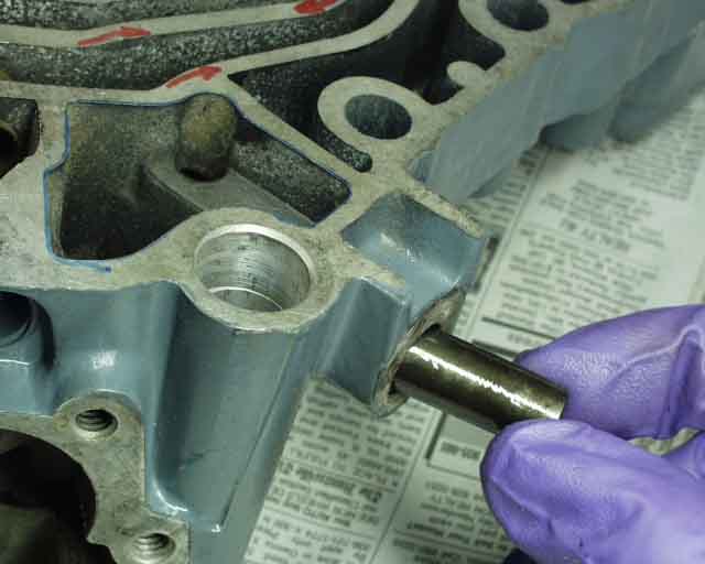
Checking and lubricating the bypass valve is a wise idea at this point.
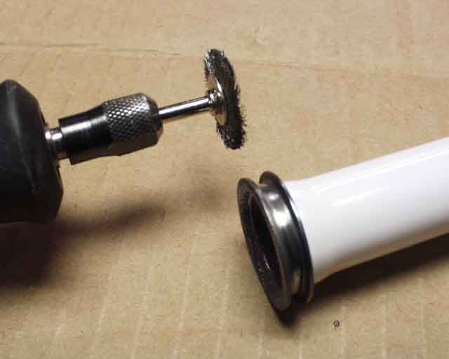
The pushrod tubes' o-ring surfaces need polishing, which I did with a wire wheel in a Dremel tool.
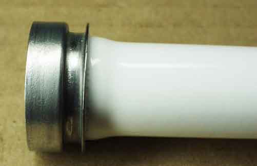
I walnut hull blasted and then had these tubes powder coated white, which makes them look absolutely brand new. But since you can't buy new ones any more (especially painted ones) I thought it was worth the $25 charge to powder coat these.
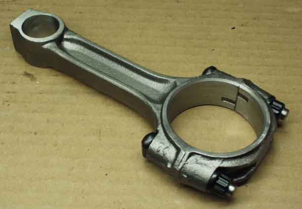
These rods are some of Bob Sutcliffe's "bulletproof" rods, which have been magnafluxed, straightened, resized, bored for VW wrist pins, balanced end for end, and shot peened. And ARP bolts were added just for good measure.
Ring gaps need to be checked like this with a feeler gauge. Specs come with the rings.
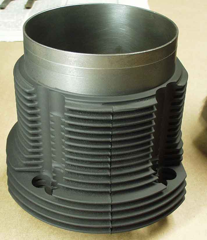
I painted my cylinders with a very thin layer of DupliColor Ceramic 1200 degree paint, and baked them in the oven at 600 degrees for an hour, per the directions. They look great.
Cylinder spacers go between the block and cylinder to space it out to get proper deck height (distance between top of piston and end of cylinder). Here I clearanced the shims with a grinder (to dodge the studs) and smoothed the burrs with a file.
Here you can see some of the machine work that Bob does on the 94mm Mahle cylinders (note the redrilled stud holes in the bottom). He also turns down the diameter at the cylinder spigot...
... and removes some of the skirt to dodge the rod from the opposite side of the engine!

See the pink and blue dots on the backs of the pistons? I think this means the pin heights are different. Upon assembly I discovered that I had more deck height on one side of the engine than the other. This may have been because of differing pin heights, and may be what Bob was thinking when he clearanced the pistons and cylinders for specific locations on the engine (pink on one side, blue on the other).
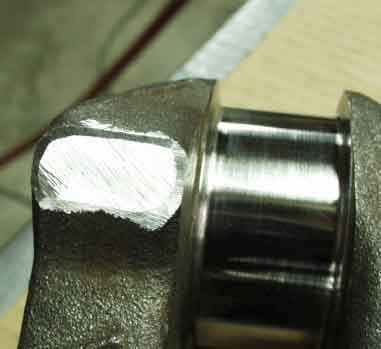
I had my crank, balancer, flex plate, and flex plate adapter dynamically balanced at a local speed shop for $150. They also checked the rods (and found them perfect) and balanced the pistons. You can see here the nice job they did of removing metal from the crank casting to balance it.
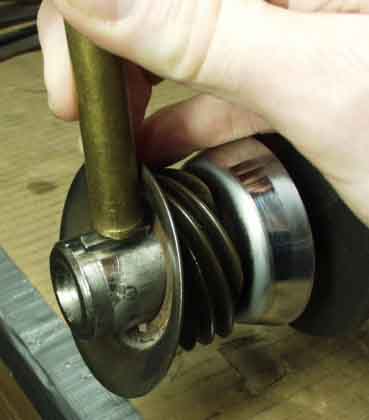
I installed a new woodruff key, using a brass drift to prevent damage to the key. The conical washer next to it is the oil slinger. The slinger can be added after the key is in place. Notice that by the time I get around to building an engine, I don't get my hands dirty!
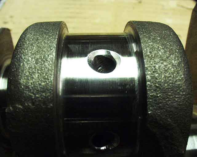
The oil holes were chamfered to improve oil flow to the bearings.
I drilled my crank flange out by hand to M10 (which is what I designed my prop hub to use), with a jig that I made by milling the mangled gear off of a bad crank gear. The two large holes are for aligning the tap, and the two medium holes are to align the 10mm drill bit. The two smallest index on existing 11/32" holes until there are 10mm holes to index on.
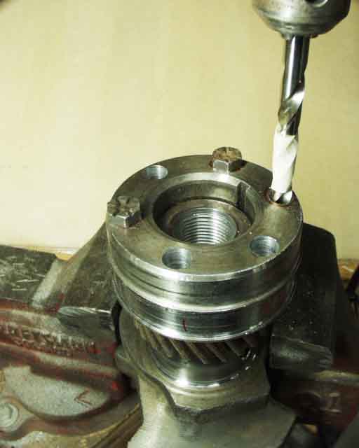
The masking tape on the drill bit was my guide to help me avoid drilling an unsightly hole into my crank gear!
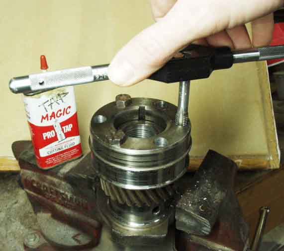
And I tapped it using one of the holes which I had enlarged to guide the tap.
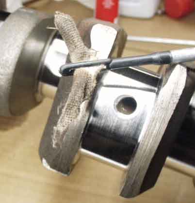
You wouldn't believe how much crud I fished out of the crank's oil passages! This was just one of about 30 patches that I ran through there, using a rifle cleaning kit that I picked up for $8 at a local gun shop. There was all kinds of metal shavings in there from the crank grinding and radiusing operations.
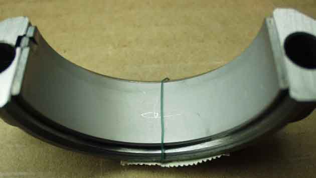
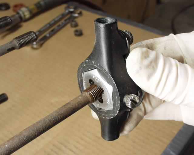
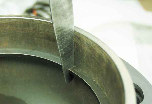
Here Plastigage is used between rod bearing and crank pin to make sure there's not too much clearance.
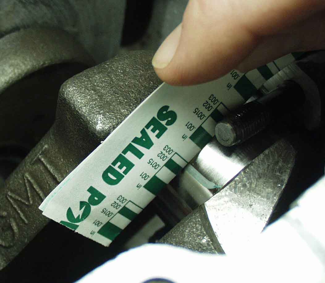
After assembling rod to crank (without rotating the rod) and torqueing to spec, the rod cap is removed and the Plastigage is measured using the scale on the wrapper. I had .003", which is right at the outer limit, but fine for an engine that will run almost wide open for the rest of it's life. I had to have this crank polished three times, since it was polished, magnafluxed, polished, balanced and chamfered, and polished again. Don't do what I did. Do this stuff first and polish it last.
Here's where the speed shop lightened the piston pin boss to bring the piston weights to within a half gram of each other. Next we need to install the pistons and cylinders and check for interference. At this stage, pistons don't have rings installed yet.
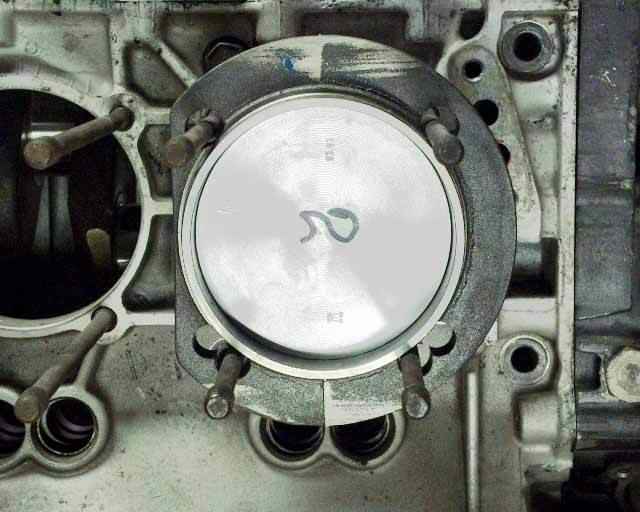
Here's the setup for checking deck height, with cylinder shims (available from Bob Sutcliffe or CB Performance (www.cbperformance.com).
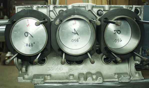
I marked all the deck heights on the pistons and noticed a pattern. It looks like maybe my crank isn't parallel to my cylinder deck surfaces, but not it's not off by much.
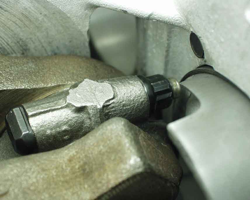
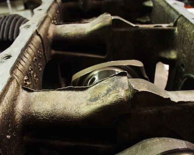
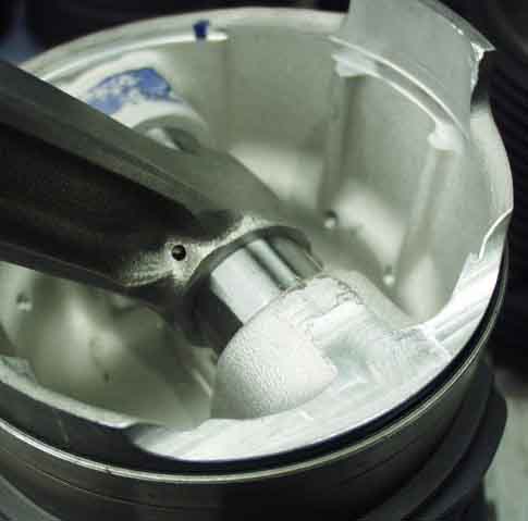
Here you can see why Bob clearances the pistons...to avoid the rod nut from the opposing side!
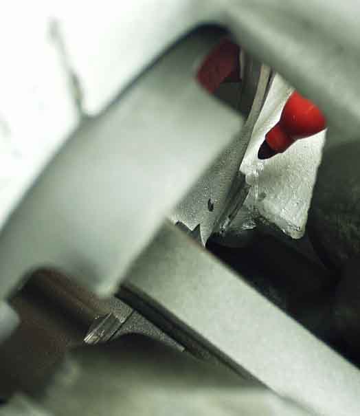
I needed to clearance the case a little more here, since the piston was hitting the case and preventing rotation.
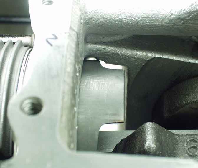
Same thing, different place.
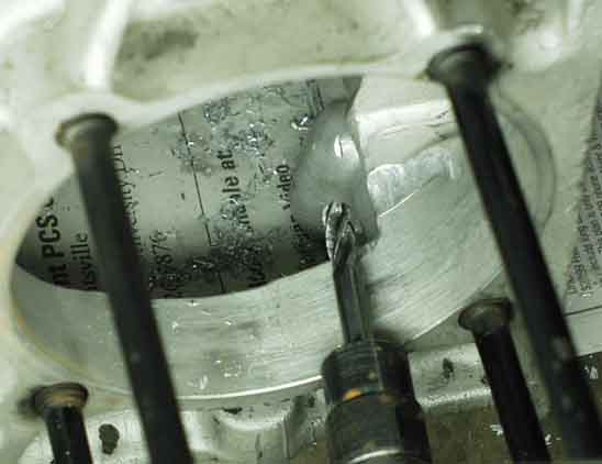
A little die grinder work took care of the problem, but with all the chips flying, I had to pressure wash the case again to get all of the chips out.
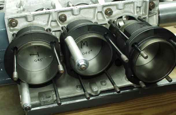
I immobilized the cylinders with spacers on the head studs while rotating the crank so that the cylinders wouldn't move in and out and bind.
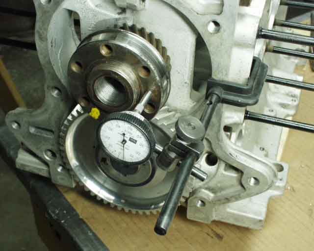
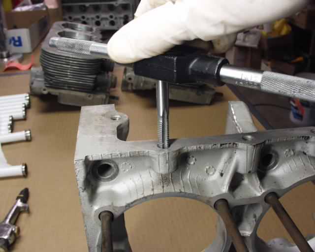
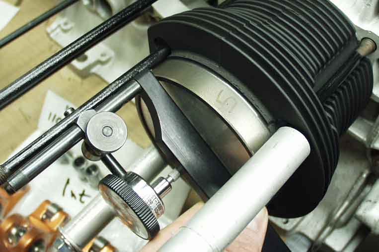
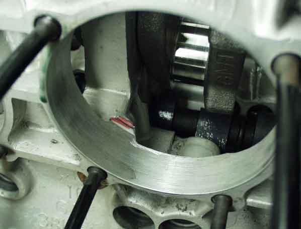
This dial indicator setup was used to check cam and crank end play after torquing the bolts. I got .004", which is right in the middle of the .002"-.006" spec. Cam gear was checked as well, and was right on!
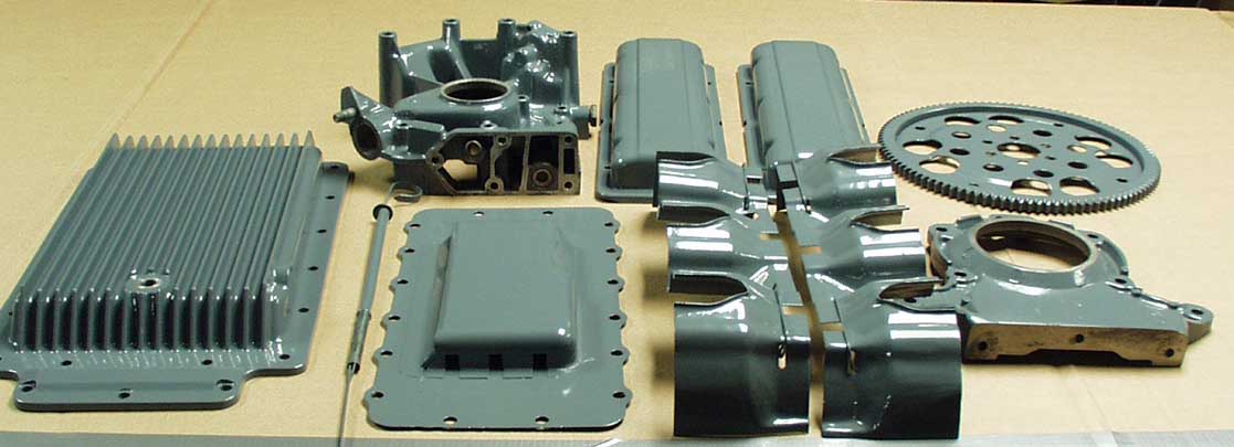
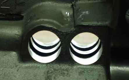
I had all of these parts powder painted for $120. It's supposedly only .0002" thick, which shouldn't impede heat transfer much at all.
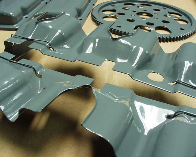
I don't think I have to worry about these rusting any time soon, and they don't look too bad either!
One of the things I did to the heads was remove all sharp edges that might contribute to preignition. This picture was made before the valve guides were replaced.
Gently rounding with a dremel grinder and then smoothing it with a dremel sanding drum or 180 grit sandpaper is all it takes. The next step is to use a Scotch Brite wheel to polish thing up a bit.
This might be a good time to try to regain my reputation as the most anal retentive of the CorvAircrafters with regards to mechanical perfection. Remember I tore my engine down to the bottom end so I could flip my pistons over so the arrow would point to the pulley end rather than the flywheel end, and also so I could mill of 7/8" of intake manifold flange to copy Pat's intakes? Well I had to play musical pistons/cylinders and basically found that swapping 1 to the 6th position, and 2 to the 5th postion, etc was the ticket. And I got lucky and had to do no internal clearancing that would have required removing the crank and cleaning things up.
Anyway, I started checking deck heights for the new combinations and everything was pretty screwed up, with a total of .007" of varience between heights using the same cylinder in all six positions. I then tried all six cylinder/piston/rod combinations in the same location, which netted an amazing .003" variance. Note that I lightly torqued the rod nuts and torqued the cylinders down to 10 foot pounds, not wanting to stress my head studs any more than I had to, but still using a uniform starting place for each measurement (see http://www.n56ml.com/corvair/02010169.jpg , but disregard the crappy welding on the fixture). This would've gotten done a lot quicker had I NOT almost welded the fixture to the studs. I had to cut the thing off without damaged the studs, which took about 2 hours! Then I started measuring my .060 shims, which mostly measured around .055", with one or two approaching .060". And it depends on where you measure, because sheet steel isn't as uniform as you'd think, so I averaged 4 readings, which I also did on each of my deck height measurements. But then they're all very "cupped" on the backside since they are stamped, so I belt sanded them flat. I wouldn't be surprised if this cupping of the spacers was the reason for some unexplained leaks around the cylinder base. Next I jockeyed shims and spacers, chamber volumes and piston/cylinder combinations, to get them all within .03 compression points of each other, which I feel is as good as I can do without grinding out the combustion chambers. Certainly "close enough for KR work"! I believe I've also decided to lower my compression ratio while I'm at it from 9.02:1 to 8.6:1, the most convenient increment without going to all the way down to 8.3:1. I base this decision on the fact that GM's test data on their 8.8:1 110hp engine was done with 95 octane fuel, and I'd like to be able to run car gas if I need to. Also there are reports that stock 110's have a detonation problem on premium, although others say it's not a problem. This thing is going to run wide open under load on takeoff and close to it at cruise, so this is a far worse case than auto use, for sure. Also, it will only cost me 2 horsepower, so I think the increase in "detonation head room" will be worth it.
It might be noted that VWs came stock with 7.3:1 compression ratio, and Great Plains says don't go more than 8:1 in their VW engines. Hapi info says use 8:1 to 8.5:1, and the Sacramento Skyranch calls anything higher than 8:1 "high compression". Then again, maybe I'm just a wuss! My Karmann Ghia's been using auto fuel at 8.98:1 for 15 years without a problem, but then I don't run it wide open for more than about 15 seconds at a time (you're going almost 100 mph at that point) but dual Webers allow a higher CR than a single carb. I lived in Vegas for two years and ran 9.9:1, and I definitely had a detonation problem during the summer until I lowered it. I ran water injection for a while, and it sure did keep my pistons and combustion chambers squeaky clean!
I ordered some .060" copper head gaskets from Bob today, so I should be putting it back together this weekend, and I can get on with cowling assembly. Some of you are probably rolling your eyes and saying "this clown's never gonna fly this thing, he's just gonna play with it the rest of his life". You might be right, but I enjoy it just the same. Getting things right is just one of those little pleasures in life that I enjoy more than most...
Next is the valve job...
Return to Mark Langford's KR2S Corvair engine.