Valve job
3100cc 110 HP Corvair Valve job
created January, 2000, updated March 27, 2005 (new Neway seat cutter tool)
The heads and case that came with my "Wisconsin" engine were pretty corroded on the outside (thanks to salty roads), so I bought another engine from a guy in Birmingham (again, for the outrageous sum of $100!). It had a "fresh" valve job on it, but I thought I should take the valves out and take a look at the quality of workmanship.
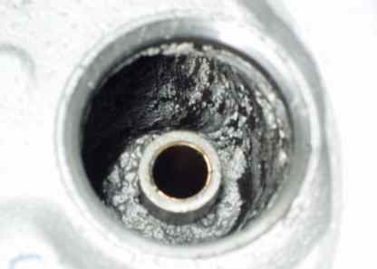
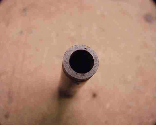
Get a look at this valve port corrosion that I found underneath! This is from water sitting behind the valve for DECADES until somebody decided to do the valve job on it! And ALL of the ports looked that way! So it turns out my externally corroded engine is in far better shape than the clean one with the heads freshly "rebuilt". It's this kind of stuff that makes me glad I'm skeptical! The guides had been reamed out to the next size and oversize valves installed, but the ports were so corroded I could never trust them not to loose a chunk of aluminum, not to mention flow problems, so these are junk. I wasn't real impressed with the quality of the "valve job" either. The stem/guide clearance was actually way too tight as well. So I used the "externally" corroded heads, which cleaned up very nicely with a little walnut hull blasting work.
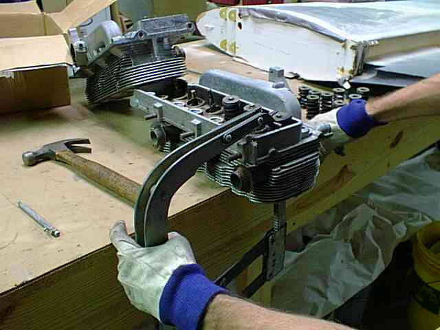
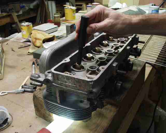
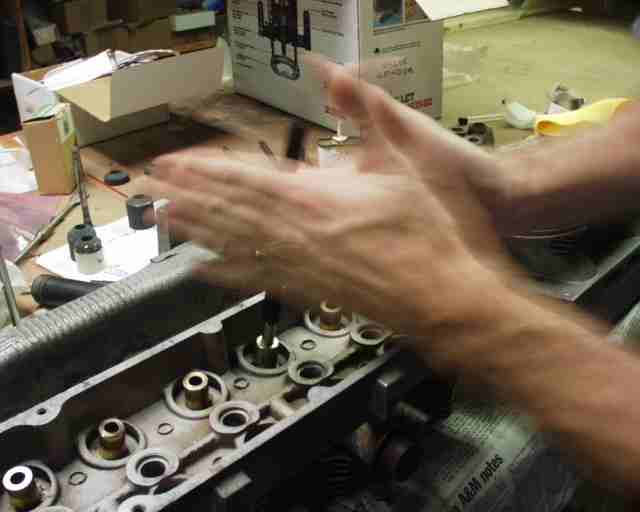
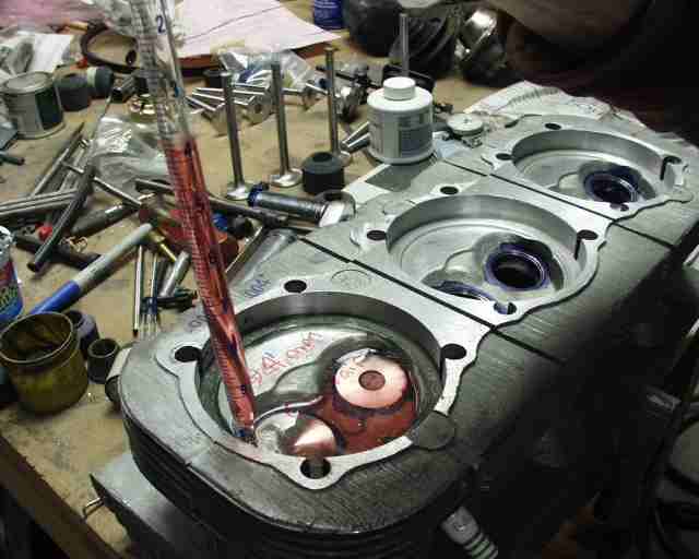
A large C-type valve spring compressor can be used to remove the valves and springs. A good whack on the top of the compressor when you get close to compressing it all the way will help break the keepers loose. No, I don't normally use a claw hammer to work on engines, but my wife was using the ballpein. What a woman!
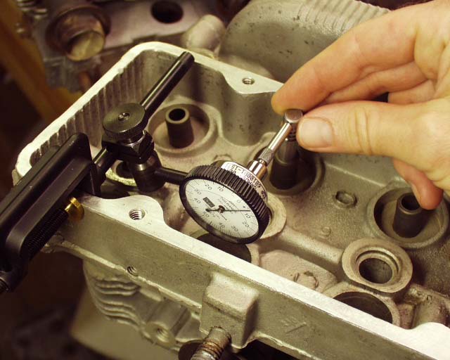
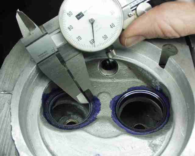
Here's the setup for measuring valve guide play. The spec is .001"-.0027" for intakes, .0014"-.0029" for exhausts, according to GM's manual. Up to .005" is OK for "used" guides, but since all of mine are more than .005", out they come. This is not something that you want to do "just to be thorough". If your guides are not out of spec, don't mess with 'em! For aircraft use, we want to be on the high side of the tolerance anyway, due to the long duration of high heat usage. And there's the matter of valve guide concentricity that we'll talk about in a minute.
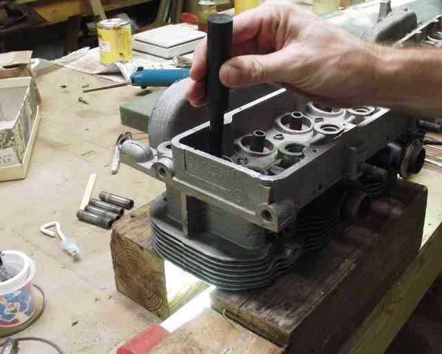
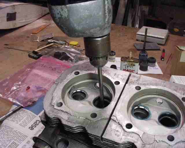
Removing guides is done with the official tool from Clarks', but you could make one from a piece of hardened steel with a lathe if you really wanted to "save" $10. Heat the head to 475 degrees in your oven for 20 minutes and drive them out into the chamber side.
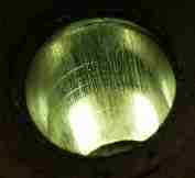
If you have been living "right", this is what your valve guide bores will look like.
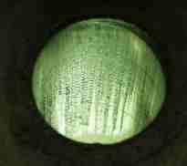
If you haven't, you might get one like this, which shows some galling as the guide was driven out. I worried about the fit of the new guide, but it was just as hard to drive in as the rest, so I'm convinced that it's just fine.
Installation is reverse, again by heating the head to 475 degrees, but they come in from the spring side, and the guides should come directly from the freezer and be lubricated with grease. That's the black stuff that you'll see around the guides throughout the rest of this page. Also, I marked each bore with an I or an X to show me where the intakes would go and where the exhausts belonged. When that head is cooling (and too hot to handle!) you don't have time to be wondering which one goes where. And I wouldn't have wanted to drive one of these back OUT again!
I chose to use the racing quality Otto valve guides, which are beefier on the top end and tapered for better flow on the intakes. Regular ones are just fine, but I like to build in all the reliability and performance that I can, since I'm going to this much trouble anyway. One other difference is that Otto guides have no provision for mounting valve guide seals, which aren't necessary or desired as long as your stem/guide clearance is up to spec.
Initial reaming is done with a hand drill and a .3420" reamer, working up to my eventual .3435", on .0005" increments. My valve stems were .3415", so that's .002" of clearance, right in the middle of the "new" range.
Before you put any of your new valves into your freshly reamed guides, make sure that there are no burrs on any of the valves' keeper grooves. I used a worn out "point" file for that job, but didn't find anything to worry about.
After reaming to the smallest diameter that you think you'll need, clean out the bore and insert a valve and check it's stem to valve clearance (like I did originally to determine if I needed new guides). Mark this valve so that it always goes back in the same guide. Tolerances on new valves are pretty close, but they are still not identical. You can use this to your advantage by swapping them around until you get a perfect fit. All of my intakes were slightly larger than my exhaust valves, which I think is a deliberate attempt to give larger clearances on the exhausts, since they run much hotter than the intakes.
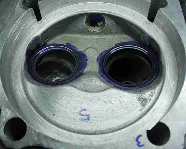
An 11/32" pilot shaft is inserted into the valve guide for a grinding stone holder to ride on. The blue stuff is Dykem machining dye, which makes it easier to see what you're doing. This seat has already had the seat cut. Astute readers will notice that this head's not been bored yet. That's because this picture was made when I was doing Mark Jones' valve job. I should have made a "before and after" shot, showing the little pits of seat erosion that would have eventually promoted "burning" a valve face.
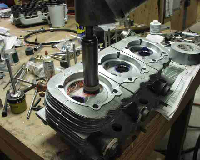
The grinding stone is spun by a special right angle drill made for the job. Here you can see the sparks flying as the seat is reground. Let the record show that this is definitely "old school" valve grinding equipment, bought cheap at a "real" garage sale, where the mechanic was retiring and closing up shop. This works fine, but is more work than the new method, the "Neway Valve Seat Cutter". See more on that at the update down at the bottom of this page.
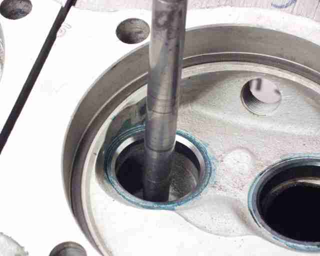
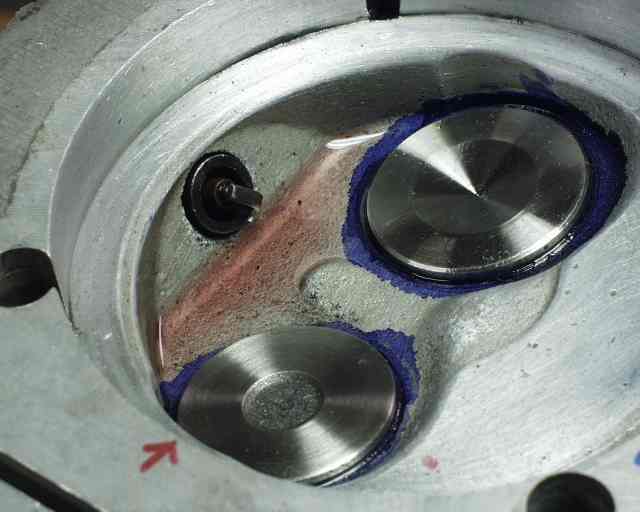
Sometimes you'll discover that your guide is not concentric with the valve seat. See how only the left half has been resurfaced, but the right side is untouched? Don't worry, it's nothing that you did wrong...
...it's something GM did wrong! At the time, I didn't know how GM managed to make a valve guide as screwed up as this one is, but I found about four of them in my head that any bozo could see were not drilled coaxial to the outer surface. But after a little extra grinding, all is well with the seat but now your valve sits lower in the head and this chamber now has more volume than the rest. Somebody later told me that GM drilled the guides out at the same time they faced the valve seats, so I guess that explains the lack of concentricity with the guides. It makes replacing the valve guides more of a chore though.
Now that the seat is refaced, you need to return it to the proper width, along with all the others.
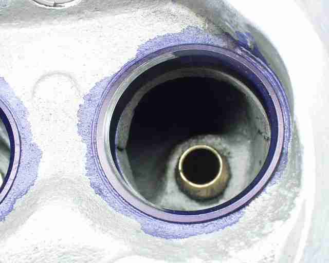
After the seat is refaced, it's painted with dye again, and narrowed to the specs (.030"-.050" for intakes, .060"-.070" for exhausts, according to Fisher's "How to Hotrod Corvair Engines) using 60 degree and 30 degree stones. It is also best to raise the contact area on the intakes so it's on the outer 1/3 of the valve face, while the exhaust face's contact area should be centered (admittedly, the photo above shows them both fairly centered, but this is a first cut...next is to move the intake seat up and out). This is what's known as a "three angle" valve job, and costs extra at the machine shop. If you didn't ask for it, you didn't get it. And you might not have gotten it even if you DID ask for it. You could argue that any flow work done won't contribute much at the low RPMs that we run at, but I can do it, so I am. But I'll be the first to admit that most CorvAircrafters would be wasting their money to go to this extreme.
Also notice in this picture how all sharp edges of the combution chamber have been removed with a dremel tool or die grinder and then sanded smooth with sandpaper. This helps prevent pre-ignition from originating at the red hot glowing sharp edges, which is very important to avoid in an engine that's going to run most of it's life near full power. Later I'll polish the whole thing to reflect heat back into the chamber and to minimize carbon buildup. I've also used the die grinder to clean up all the gross casting flaws in the ports, and radius the ports in places where it's obviously needed. I also used 600 grit sandpaper to round the edges of the valve seat cuts to improve flow there. But unlike the three angle valve job, anybody can and should round off the sharp edges in the chamber to prevent pre-ignition. A couple of sheets of sand paper is all you need. Also note just below the right valve there's a little area of casting that wasn't quite removed when the head was bored for the cylinders at the factory.
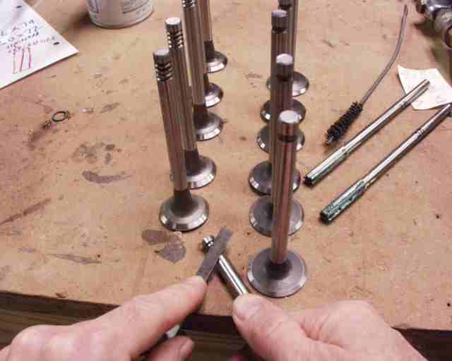
The valve facing work is to "lap" the valves using valve grinding paste. A little of this abrasive concoction is spread on the valve seat and then...
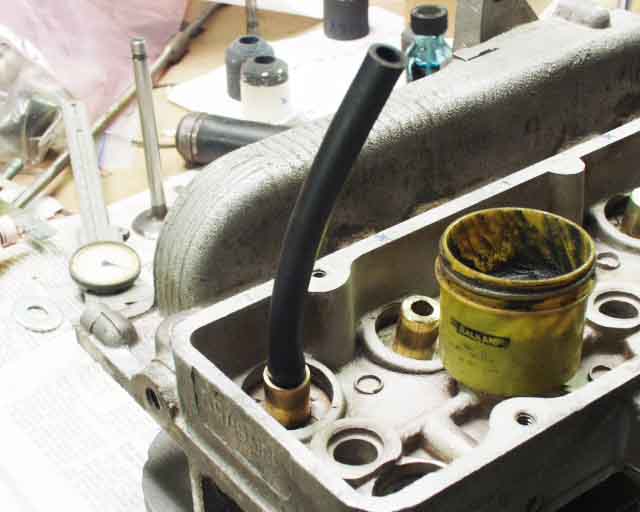
a short length of rubber hose attached and then...
pulled upward and rotated to "lap" the valve to the seat, making a perfect seal.
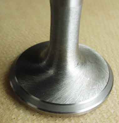
The resulting indication of where the valve seals is clearly visible on a new valve, but Prussian blue dye (Dykem) is helpful if the valves are used or previously lapped. Check to ensure that the contact area is the proper width and stays that way all around the face, although it almost HAS to at this point! If it's not, it's because your valve is bent! It looks like this one can stand a little seat narrowing still, but the contact area is centered, as it should be for an exhaust valve.
These valves are Corvair Underground's stainless steel swirl polished valves, with chromed stems and stellite faces. They are only slightly more expensive that the other stainless valves, at around $10 each.
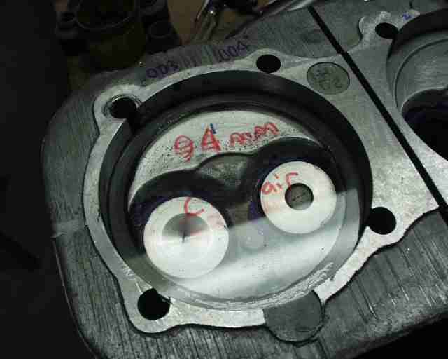
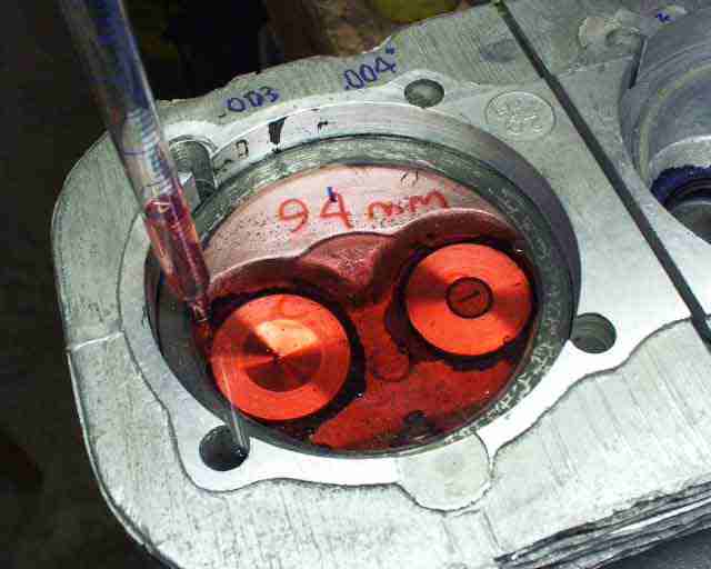
Next you need to "cc" the combustion chambers so that you can set up your desired compression ratio. First install a sparkplug and torque it to specification. This is a good time to find out if you need to Timesert a plug hole, rather than AFTER the engine is assembled. Then install the two valves with a thin coat of grease on the faces to prevent leakage. Next I cut a disk out of 1/8" plexiglass, and drilled two holes in it, one the size of my pipette and the other for an air escape hole. A thin film of grease is smeared around the edges to seal the chamber, and the plate is inserted into the chamber and rotated a little to seal the grease. Level the head with a torpedo level across the machined fin surface. I wrote "94mm Corvair" on it to identify it from one of several others I've cut over the years, mostly for VW work.
I used kerosene for this, since it flows easily and is visibly red. Some people use ATF but it's far more prone to having bubbles get stuck under the plexiglas and mess up your readings. I sucked the kerosene up into the 10cc pipette and quickly held my finger over the top end and gradually released pressure to drop the level to where the miniscus (the lower edge of the U shaped top surface of the column) read exactly 10cc (or ml, same thing), making sure that I was viewing the pipette directly from the side, while the end was still submerged in fluid. Then I transfered the pipette over to the plexiglas disk and released my finger to empty the contents into the chamber.

Do this four times, watching the bubble of air and making absolutely sure that the fluid doesn't escape out one of the holes, just the air. This is where previously leveling the head comes in handy. I also keep a wooden "builder's shim" (for shimming doors and windows) under one edge of the head for minor corrections to keep the bubble headed up toward the air escape hole. Be careful not to get carried away though, because when you remove the pipette to reload it it might come out THAT hole, so you want it just slightly out of level biased toward the air escape hole.
When the air bubble disappeared completely, I had released 48.3 cc's into the chamber. The second one was 48.7 ccs and the third one (number 5) is 49.1. That's in line with my theory that GM didn't bore this head the same depth on all three cylinders. Maybe the valve cover surface isn't in the proper plane assuming that's the flat surface they use when milling the chambers for the cylinder bores. The other head is 47.5,47.8, and 47.8. Now all I have to do is find the largest one, and remove a little aluminum from the five smaller ones so that they all match within .1cc.
I wanted to get an idea of how much 1cc of volume looks like, and this is a picture of it. Right now I have a spread of 1.6 ccs, so I have some work to do. I may only do one more iteration, but the result will be combustion chambers of similar volume, which will give me similar power from all six cylinders. And more importantly, I will KNOW what my compression ratio is, rather than guessing. This is part of the "blueprinting" process of eliminating manufacturing tolerance stackup. You might have noticed that my cylinder number 5 (about 10 pictures ago) either wasn't machined to the same depth (by the factory) or the casting wasn't quite as tall, so there is a definite need to see which is the case.
But if for no other reason, you need to cc at least ONE chamber (the middle one) from each head so that you can average them and calculate your compression ratio and adjust it with shims to whatever your desired CR is. I'll make mine 9.25, just like the stocker,which is rumored to have actually been closer to 8.25 by Fisher, despite the factory claim. [Mine eventually ended up at 9.02:1, which is fine with me]. Even the GM specs listed on my web page list the CR as being in the 8.7:1 range. Keep in mind that even IF the factory CR claim was correct, boring out to a larger diameter piston automatically raises the CR somewhat. Incidently, when Bob Sutcliffe bores out the heads, he stops just as soon as he "cleans up" the stock bore depth on the deepest chamber, then bores all the rest to the same depth, just in case you were wondering.
Project Update - as of Jan 14, 2001

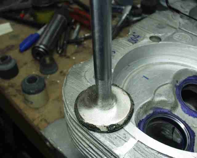
The next step is to measure how far the piston is down inside the cylinder at TDC to get the "deck volume", which is used along with cylinder volume and chamber volume to calculate the compression ratio. The setup above allowed me to determine that it was a mere .0015" with no shims between the cylinder and engine case.
The quick course on compression ratio is that the CR=(chamber volume plus deck volume plus cylinder volume) divided by (deck volume plus chamber volume). But the easy way to do this is with an Excel spreadsheet that I found on the web after entering the numbers for the 94mm VW big bore Corvair that I'm building. The spread sheet makes it a breeze to run various "what-if" scenarios involving combustion chamber volume and cylinder shim thickness.
The spread sheet allowed me to quickly determine that if I could enlarge the two smaller volumes of each head to match the largest one (49.1 cc on one head and 47.8 cc on the other) that I could use the .010" cylinder shims that Bob Sutcliffe supplied with the kit on one side only, and add a .040" 94mm "barrel shim" (from CB Performance) under all six cylinders to get 9.217:1 on one side, and 9.213:1 on the other side!
But later after mounting cylinders and pistons with barrel shims under them and accurately determining deck heights, I discovered that the deck heights on one side of the engine averaged .058" on one side and .043" on the other! Once again, all I had to do was put the head with the low average volume on the side with the larger deck height, and the other other head on the side with less deck height, which evened everything out and kept me from having to completely equalize the volumes of all six chambers.
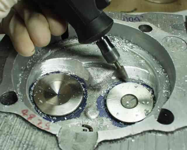
I set about grinding out chamber volumes to equalize them. I found that the easiest place to remove material is along the wall on either side of the sparkplug hole, and "unshrouding" the valves by removing a little of the walls that extend from valves up to the "squish" chamber (the flat part). The big work I did with a die grinder, finished up with this dremel tool, then sanded the rough edges smooth with sanding drum and paper. The end result was that I got two of the three on each head exactly the same, with the other being only .1 cc off! Close enough for KR work!
This chamber volume matching effort took about 5 hours total, with me measuring each chamber 3 or 4 times (except the largest "target" chamber on each head, which I only measured once to double check). You'd be amazed at how accurately you can measure these, with repeatability. Don't forget to blow out the spark plug before each measurement to remove the fluid that runs down inside it, and around the valve heads to flush out kerosene from around them, as well.
While these numbers are very close, don't lose sight of the fact that a .010" difference in gasket thickness makes a difference of almost quarter of a point, so it's very important to get this right, especially side to side. A difference of .040" shim thickness, or the difference of 8cc of chamber volume is enough to change the cr from 9:1 to 8:1! My heads will use .030" copper head gaskets between cylinder wall and combustion chamber, yielding a compression ratio of 9.1 to one on each side. [August 2004- The compression ratio has since been lowered to about 8.4:1 until flight testing proves that I can safely raise it back to 9:1.
later... Conventional Corvair wisdom is that best resistance to detonation is obtained by keeping the total deck height (distance between top of piston and the head's flattened "quench area") at somewhere between about .042" and .025". This kind of close quench distance allows running higher compression, lower grade fuel, and more "headroom" before the onset of detonation. You can usually get in this range by using .010" cylinder base gaskets, .032" copper head gaskets, and unshrouding the valves to provide the larger chamber volume required to keep compression ratio reasonable. If necessary, you can also machine up to about .030" off selected parts of the piston crown, or just have custom pistons made that incorporate a bigger dish if he needs more volume. See more on this subject down below, in a post made to the CorvAircraft mailing list.
Next comes the question of valve spring tension.
I guess I just want to know every stinkin' detail, but there were a few details missing when it came to spring tension for the valve springs that I was planning on using in my engine. I had originally planned to use Clark Corvair's "high performance" springs, number C8619. Later I bought a set of Bob Sutcliffe's Isky springs and titanium retainers, probably because I liked the idea of saving a little weight, and thinking that whatever Bob said I needed, I needed.
While installing Bob's Isky springs I got the impression that my valve spring compressor sure was working hard, and started wondering about spring pressure. Knowing that I'll never turn over 4000 rpm with this engine, and that any pressure over and above that required to prevent valve float will do nothing for me but cost power and accelerate valve train wear, I ordered a set of Clark's "stock" springs, thinking they would be just fine for what I'm doing.
Properly installed, Bob says his are 90-100 pounds at 1.74" installed height (bottom of retainer to top of spring seat), but he gives no numbers for when the valve is open. That's probably because he doesn't KNOW what kind of cam you're going to use, but I DO. It turns out that with the minimum thickness spring shim (the .032" thick stainless one that Clark's sells) my installed height was 1.725". The GM manual calls for 78 to 86 pounds at 1.66" installed height and 170 to 180 pounds at 1.26" (valve open). Since I'm using the OT-10, my max lift height will be .424 (average of .413 intake and .436 exhaust) less than my zero lift height, which is 1.301".
I started wondering what Clark's "stock" springs were like, and ordered a set. They came in yesterday, so I scurried down to the speed shop and talked them into checking one spring from all three sets, at both .166" and .126", since those are the numbers listed in the GM manual. He came up with:
                 installed       open       coil bind

"stock"           100#           205#         .096"
Isky              130#           230#         .379
HP                140#           265#         .093
He also agreed that since I'm never going to exceed 4000 rpm, the weaker stock springs were the way to go. What worried me about the way he tested them is he never used the titanium retainer on the Isky double valve spring. He just measured it (.098" thick) and adjusted the height that he checked the pressures. This bothered me because it failed to take into account the step that the second spring rides against.
So, there was only one way to find out for sure what was going on...make my own spring tester and test them myself.
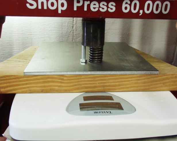
This scale is digital and claims an accuracy of plus or minus half a pound from 25-300 pounds. Results are certainly repeatable, as you can see from the notes I made below. When you can hit the same number 3 times in a row, you've got it down to a process! At first I was going to measure all the valves with a random amount of deflection at two different heights and calculate a spring constant, but the shortened inner spring of the Iskys probably wouldn't have been linear, so I decided to set up a zero lift and valve open test for all three springs. I really wasn't up to juggling all the variables in my head at one time, which is why I resorted to sketches of the setup required for each sample.
I used the bolt as a height gauge and shimmed below either the spring or the bolt to get the compressed length to match exactly my zero lift and valve open spring heights on my engine, and then the bolt was slid out right before the reading was made. This would have been a whole lot easier had I owned a dial caliper that sits on a flat surface. Maybe next weekend!
And I used the same titanium retainer on all tests to eliminate that variable, and to put the inner spring to work for the Iskys. The process went as shown below. It's easier to read if you print it out, but I believe you'll agree that I did the job correctly, replicating the real world situation that the springs will experience. The shims were aluminum or steel sheet, along with sheets of paper (.005" thick), of which the most I ever had to use was two sheets.
The bottom line is that I think the stock springs might just work fine, with a spring pressure of only 85 pounds at zero lift, and a valve open pressure of 217 pounds. Clark's aluminum retainers are almost an exact swap for the stock steel ones, except they reduce the installed height by .017", increasing pressures slightly. Bob cautions that the "stock" springs are made offshore somewhere and that they might not maintain their pressures as long as the Isky springs do.
Bob Sutcliffe's Isky springs using titanium retainers are also a viable option, with only 105 pounds of pressure at rest and only 222 pounds at full lift. His springs have the advantage of being dual, so if one breaks the other will still work, and they have loads of room between the coils. And they are made of the best material for the job, and are of the highest quality. They cost $80 rather than the $30 for the stockers, and the titanium retainers are another $80, vs. $42 for aluminum ones that Clarks sells.
The High Performance springs from Clark's are way too much pressure for a 4000 rpm engine, with 137 pounds at rest and over 300 pounds at full lift (my scales start flashing 8888 at 300). Accelerated valve train wear and higher internal friction numbers are all you'll get with this setup.
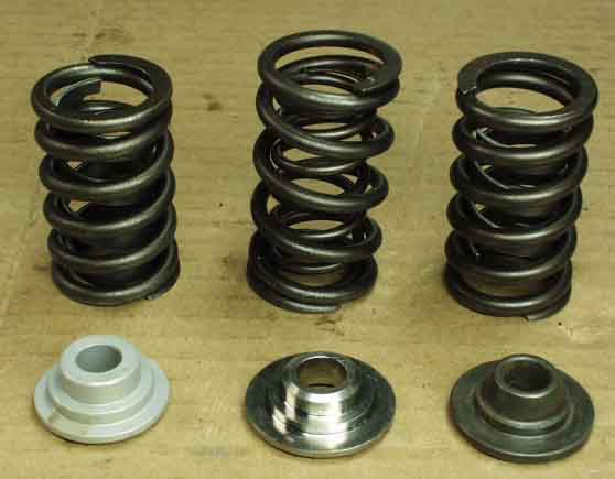
The contenders are stock spring, Isky spring, and HP spring. Also shown are the aluminum retainer (8.5 grams), titanium retainer (11 grams), and stock steel retainer (22 grams).
Since I already have Bob's Isky springs and titanium retainers installed, I'm going to leave them there. And I like the quality and larger coil binding distance. But if I were starting from scratch, I might just try Clark's stock springs with their aluminum retainers. I think either way will probably be just fine in our low RPM range.
If you get the impression that a GOOD valve job is time consuming, you're absolutely right! I've got 18 hours in the guide and seat work, and that's not counting cc'ing the chambers. That's why I seriously doubt that you can pay ANYBODY enough money to do this job correctly, so you pretty much have to do it yourself. And you may PAY for a "performance valve job" but I'd sincerely question whether or not you'll actually get one! The problem is that when somebody brings in a head for a valve job, the mechanic immediately knows that you don't have what it takes to do it yourself, and after it's put back together, you can't tell what's been done!
The last time I gave that speech I ended up doing Mark Jones' valve job, but trust me, I'm definitely NOT looking for anymore valve jobs to do!
The question of quality reminds me of Jim Hill's engine. When I first met him he complained
that it took forever for his "rings to seat" in his KR2. It seems his 2180 ran like a
3.5 cylinder for the first 50 hours, then smoothed out, but at 100 hours it
became a 3 cylinder. He went thru this 3 times, each time getting a "valve
job" from a supposedly reputable engine builder, until I insisted he let me
look at his heads. First thing I did was notice that one of his valve
guides had a lot of slop and the seat was quite eroded, so I knocked out
the guide, and went to the freezer and got a new valve to drive in it's
place (yes, I keep a box of VW guides in my freezer at all times). When I started grinding the seat, the stone only gound one side,
sort of crecent shaped like my example above! Hmmm.
It became obvious that the guide boss was not coaxial with the
seat when the head was manufactured. I ground the crap of it until it
sealed, but I couldn't help but wonder what mechanic bozo would do a "valve
job" and not even bother to blue it and lap the valve, which would have
graphically shown the total lack of seal between valve and seat.
What was happening was the valve wouldn't seal, but the side forces on the
valve would eventually elongate the bore in the guide until it did seat, and
it would start running better, usually after about 50 hours. But then that
slop in the seat would allow it to wobble around and wear the valve face and
seat excessively until it needed another valve job at 100 hours. Happened
three times, just like clock work.
This was the first time I'd ever seen this phenomenon on a head straight from the factory, but somebody else had
THREE opportunities to notice it before I did. This is just one of the
many reasons nobody touches any of my cars but me (not even my wife's new Audi A4 Quattro, which is under warranty for 50,000 miles). But don't get me started on the subject of paying "professionals" to do something for you!
Here's a compression ratio spreadsheet that I made up for my engine that you might find handy.
Here's a post from Ray Sedman that says a lot:
Date: Aug 27, 2004 2:16 AM
From: Ray Sedman
Subject: RE: CorvAircraft> Head Mods
----------
Just a few points regarding the discussion on heads:
1. There is not enough chamber depth to add significant squish
area to an open chamber head like a smog or 65-6 turbo head while
keeping a tight deck and a low static compression ratio. For the
cost of the welding and machining, one would be much better off to
just start with a wedge chamber head.
2. I do not concur that a 110 HP or 102 HP head performs worst
than a 95 HP head given the same static compression ratio [C/R].
In fact, testing I have done has shown that the chamber design of
the 102 HP head will perform better than a 95 HP head when used in
high compression engines with long overlap camshafts. In low to
moderate compression engines with mild camshaft timing, I have
found no difference in power output between any of the small
valve, wedge heads given all other things being equal, e.g., deck
height, static C/R, etc.
There is no subjective reason why one could not use an early wedge
head (61-3) and bore out the gasket register to accommodate the
late cylinders. There are just a few wedge chambers that the
Vair ran and ALL of them can be used in the same manner. You just
need to adjust your C/R to your target goal based on the chamber
you are running. You can easily make a 110 or 102 head look and
work like a 95 HP head. It just takes some work with a die
grinder. There really is no magic here. For example, the early
80 hp head has the same chamber as the late 95 HP head. You would
just bore out the early head counter bore to fit the [larger] late
cylinders. For me details on this, check the archives. I posted
some detailed information regarding this some time back. If you
can not find it, let me know and I will send it to the list again.
3. When welding the chambers or re-making the chambers as with my
high squish modifications, one must be careful regarding the valve
seats. My personal rule is that I will not do extensive welding
on the chamber with the stock seats in place. I feel there is a
greater risk of loosing a valve seat after the head has been heat
cycled in this localized area. For this reason I will not do
these modifications with out replacing the stock valve seats.
4. There are a few other ways of obtaining a low C/R and a tight
squish band with out resulting to welding the head or milling the
gasket step all the way down so there is a minimum wall thickness
above the spark plug boss. It all depends on what your goals are
and your engine configuration. I have built three liter
turbocharged engines with .035" total deck while achieving a
static C/R of 7.5:1.
Cheers!
Ray Sedman, Corvair Performance Parts and Services, SM
Project Update - as of March 27, 2005
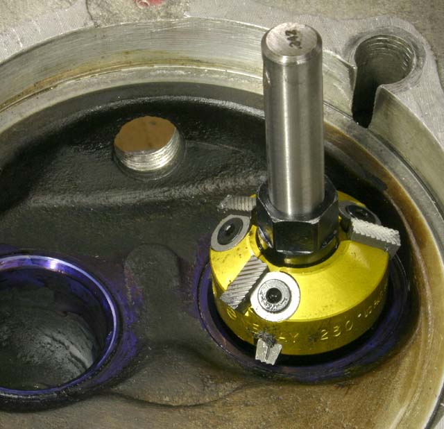
Neway cutters are high precision carbide cutter heads that work way better than the stone method, and they are relatively cheap. It turns out that you can buy one cutter head that will cut both 45 degree and 30 degree surfaces, so one cutter will almost get you there. But another 45/60 and you'll have the whole deal, and each cutter is adjustable to cover both intake and exhaust valve diameters. Grand total for two cutters, a pilot, and a thing to turn them with is about $250, which is not bad to be able to do your own three angle valve job, again and again. In the photo above, I'm cutting the 45 degree seat, so the cutters are slid out to meet the face. The blades facing up are on the 30 degree side of the cutter. This cutter is number CU230. You'll probably need an 11/16-1 pilot #PF140-11/32-1 (or 11/16 pilot #PF140-11/32 depending on what you ream your guides to) , and a TW505 wrench to turn the cutter. You'll also need a 60 degree cutter to do it right, so you'll need a CU273, which has a 60 degree on one end and a 15 on the other. Call Linda at Neway (989-743-3458) to order. I'm posting their phone number because their web page is hard to find, not much help, and gives you the impression that they don't actually sell to the public, but they do.
Next step is engine assembly...
Return to Mark Langford's KR2S project.