Mark Langford's KR2S Trim Tab
KR2S Trim Tab
created Jan 5, 2003
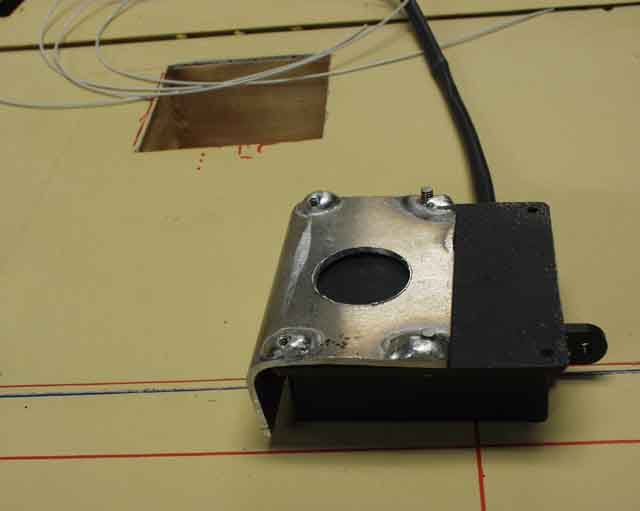
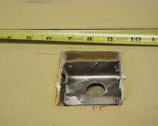
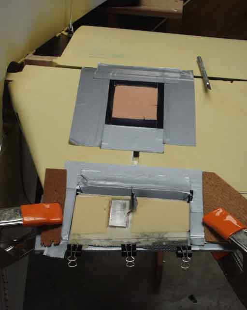
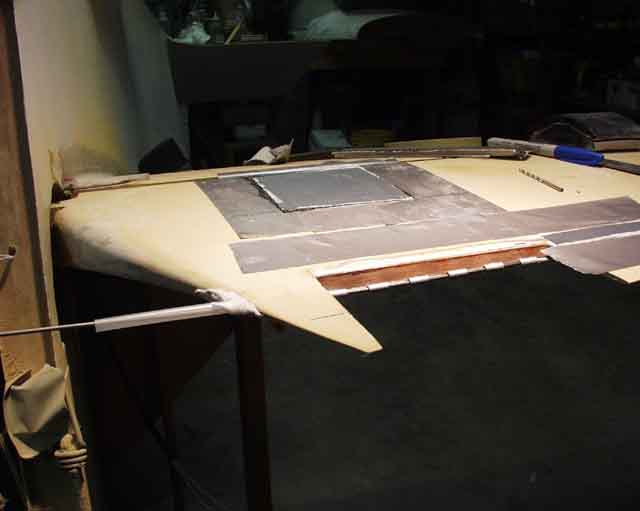
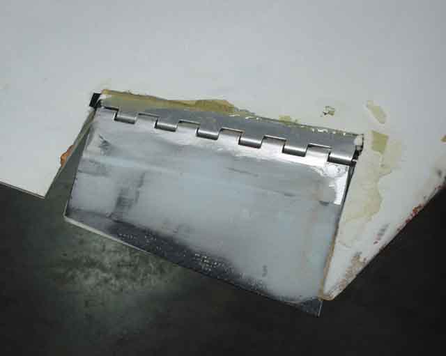
I started by cutting a hole in the skin big enough to fit the trim tab, which was not as easy as you'd think since I made it out of two layers of 5.85 ounce fiberglass. I then made a bracket to hold the MAC -4A servo (which is now the RC Allen something-or-other) to the aft of the elevator spar. This servo has about .75 inches of travel, and has built-in limit switches that cut power at the ends of extension. The blobs of aluminum melted onto the bottom are my pathetic attempts to create "bosses" for extra thread engagement for the #6 mounting screws by TIG "welding" on the bottom of the bracket. This "bracket" was fished out of the recycle bin at work, and was bent another 10 degrees by the time-honored method of vice and hammer. You can see that it bent halfway through the servo side, since I didn't have the foresight to bend it before I cut the lightening hole in it. The lightening hole saved me 8 grams.
The three number 4 wood screws are only there to hold the bracket in place long enough for the T-88 to cure. I roughed up the aluminum before I epoxied it to the spar.
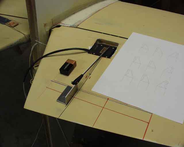
I mocked up the threaded pushrod and the bellcrank, along with several versions of how big I thought the tab should be. The plans say 4" x 10", but I thought 3" by 6" would be plenty since my CG just barely varies from full fuel to empty, thanks to my use of wing tanks rather than a header tank. I'd have made it even smaller, but I started thinking about trying to land the plane with the elevator cables diconnected (using only the trimtab), so I left it larger than I'll probably ever need.
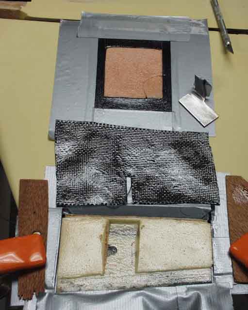
I really should have used a longer hinge that extended all the way, just to make it look decent, if for no other reason. I clamped a quarter inch thick piece of 6061 under the hinge, enclosed in duct tape, to hold the hinge flush with the "top" of the stabilzer (bottom, here), then floxed it in place. I covered the hinge itself with tape to keep epoxy from siezing the hinge (been there, done that). The
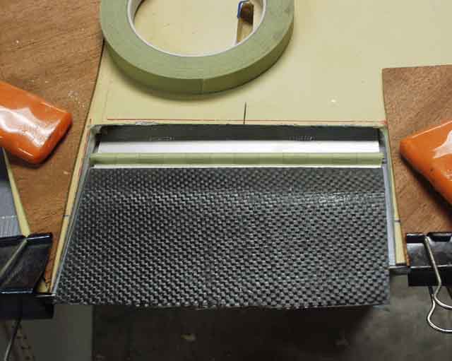
I found this scrap of 5.85 ounce carbon fiber that I'd layed up on a flat piece of aluminum years ago, and it just happened to have a joggle in it that mated perfectly with the piano hinge. I floxed it to the "tab" end of the hinge, again taping over the hinge itself to keep epoxy out.
Next I microed on a scrap of 3/8" thick 4 lb/ft3 Lastofoam to the carbon fiber...
...and sanded it flush with the horizontal stabilizer.
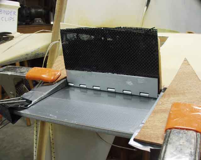
The result was, well, "good enough for KR". I'm not sure if 95 degrees is enough deflection though. This picture reminded me that I missed another opportunity for lightening holes. These could have weighed a third less, and would have been retained better (not that I'm worried about that).
Then I hogged out some foam to bed the bellcrank into contact with the top skin. And while I was at it, sanded some urethane foam flat over the servo to aid in making a cover plate. This positively connects the top surface to the bottom surface (along with the "healed" edges on either side) and to the bellcrank. After looking at this photo, I realized that I missed an opportunity for a huge lightening hole in the middle of the flat part of the bellcrank.
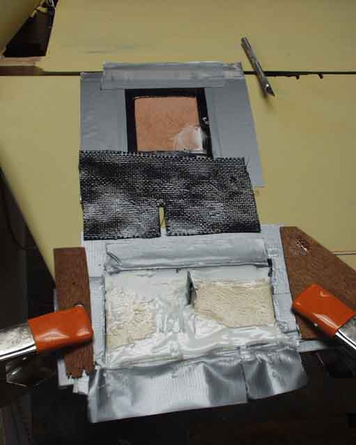
I cut scrap of carbon fiber to fit and microed the bellcrank in place...
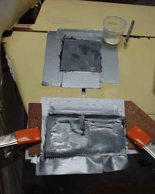
... and topped it off with the carbon fiber. I also laid up the servo cover out of two layers of scrap carbon fiber. I built my wings out of carbon fiber, so I have a lot of triangular 6 ounce carbon fiber scraps.
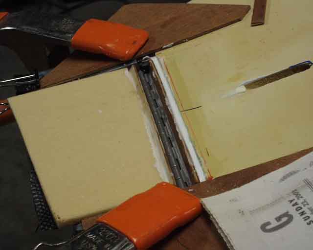
I microed a piece of scrap mahagony (I don't throw ANYTHING away!) in place to act as a dam to keep the micro out of the hinge pin area. If I'd done my homework and cut the hole the right size to start with, I could have saved all of this weight. On the left you can see the .090" hinge pin (they sell this stuff separately at Wicks and AS&S) and the Nylaflow guide tube that I microed in place. If I ever want to remove the trim tab, all I have to do is pull the pin on the clevis, remove a little retaining screw, and slide the pin out, and it falls off.
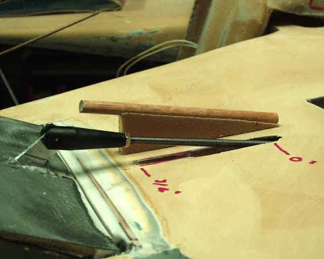
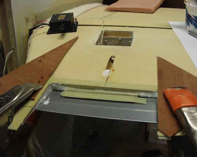
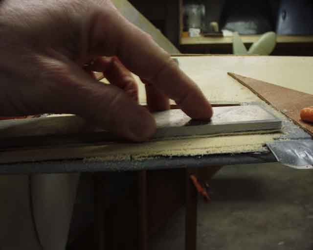
Here you can see where I marked the limits of pushrod travel as it extended from 0 to .75". I madestarted a fairing to enclose the bellcrank and pushrod, made by wrapping a piece of "plyfoam" and a wooden dowel with duct tape, and laying up two layers of glass over that to form the fairing. This is not going to do any good aerodynamically, but I DID want to keep grass, bugs, and water out of there. Plyfoam is just a nickname for a piece of foam with glass laid up on both sides.
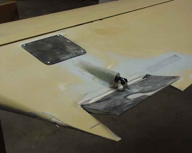
The servo cover will utilize countersunk screws, and I've faired the front and rear edges to keep the flow smooth over it.I accidently used Super Fil (the blue stuff) to smooth everything out. I didn't remember how hard the stuff was to sand until I was sanding it. I like Aeropoxy Light better, because it spreads in place better and sands easier. I have plenty of it, just forgot to use it.
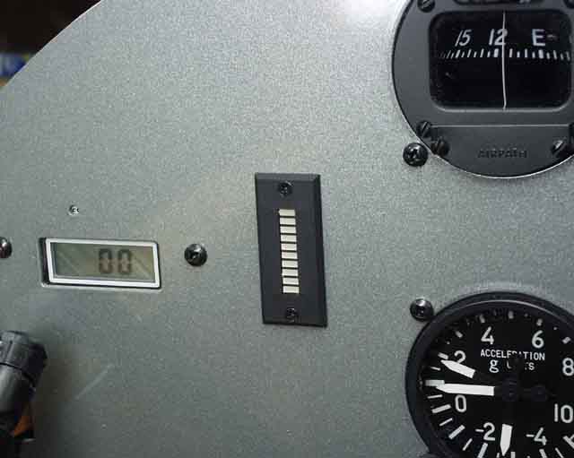
Here's the LED indicator mounted on the left side of the instrument panel. There's a vinyl face that sticks on around the column that says UP and DOWN on it, but until it's wired I won't know if it's upside down or not, so the legend will have to wait. There's a cable consisting of five 24 gauge stranded copper wires running back to the trim tab from the stick, and another six wires running from the indicator to the stick switches. I'm using the MAC stick grip which has the trim UP and DOWN buttons on the top. Pictures of that are pending installation. The LCD display to the left of the trim indicator is the "Tiny Tach" digital tachometer. That battery is only good for seven years. I hope I'm flying before I need a new one!
Here's what it looks like from the top at maximum deflection, which is 23 degrees up, and 23 degrees down. I can easily bias that in either direction later by changing the length of the pushrod, as I suspect I'll need most of the tab in the DOWN direction, since adding a passenger will require it. Now if you'll excuse me, I have a little finishing work to do...
UPDATE, 2014 - After flying N56ML a few years the three LEDs slightly "north" of the
middle are now dead, killed by radio frequency energy. I noticed from
the beginning that keying the mic lit whichever LED the indicator was
pointing at, above and beyond the normal level. Eventually it killed three
of them depending on which one was "indicating" at the time. I attribute
this to either the fact that my trim servo wiring ran along with the radio
coax for a few inches before separation, and even more likely, because the trim power/signal wiring has a junction right at the center of the vertical
stabilizer spars, which is where my radio antenna also split into two legs
of the dipole. There's lots of power exiting the plane, at that point!
With this in mind, when I rewired N891JF, I replaced the trim tab wiring with shielded cable
(grounded only on the panel end). I also kept it well clear of the radio and ran it along the bottom longeron to avoid the coax at the top longeron. The servo is located a couple of feet from the antenna in the tail, so I doubt I'll have problems with this one!
UPDATE, 2020.... Well, I fried the LEDs in N891JF's trim indicator also, so I have arrived at the conclusion that it's simply the antenna being so close to the trim tab that kills them. So don't bother shielding the cable...maybe put the antenna somewhere other than the tail, like maybe in the middle of the turtle deck (longitudinally), and against the fuselage wall opposite where the cable runs (probably the passenger side). Maybe that'll make it, but no guarantees! I guess if the actuator AND the cable are both shielded that would work....and somebody's welcome to try that....
Return to Mark Langford's KR2S project