revised July 16, 1997
Before beginning your vertical stabilizer, you must have your horizontal stabilizer fastened in place. This is because the v.s. forward spar bolts to (and traps) your h.s. front spar. If there's anything you haven't done inside the fuselage below the h.s., do it now, because you won't be able to get down in there later. I deliberately avoided installing the the tail surfaces until now because they eat up a lot of work area. I'm only installing them now because I need to install control lines from the stick to something. And I'm eager for the thing to look like an airplane, rather than a space age boat.
One thing that's not shown in these pictures that SHOULD have been there was my com antenna. I should have glued it to the front vertical stablizer spar, extending to the very top, with the coax bisecting it several inches up from the bottom. In fact, I even sent a message to KRNetters reminding THEM to do it, and promptly forgot to install it myself! Visit my panel page for how I was forced to do my antenna later (and HOW to build the antenna itself), but you really should take the time to glue the copper strip to the stab now and run the coax to it. It works better facing forward, and you can make it much longer (without having to bend the tips to get 41"), if you stick it to the front face of that spar. If it turns out that it doesn't work later (which is unlikely), you can still do the kluge job that I did.
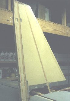
I used a method of jig/template/ribs that I developed during construction of my horizontal stabilizer to maintain perfect alignment of rudder to vertical stabilizer, as well as of the assembly to the fuselage. Although I used a different airfoil, this same method could easily be used with the plans' version "airfoil". By rigidly mounting all structural members of the v.s. in perfect alignment before installing foam or hinges, a perfectly continuous airfoil is almost guaranteed.
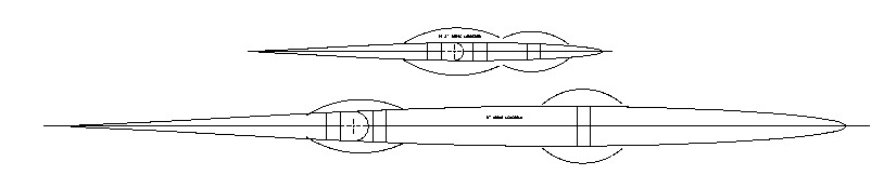
First I plotted the coordinates of a NACA 63005 airfoil and fitted a 3rd order bspline curve through them to create an accurate airfoil outline. Although this JPEG image looks pretty jerky, the real airfoil template is very smooth. Spars and a centerlines were drawn in to aid in alignment. The key to these templates is to leave extra material (humps) around the spar cutouts, so that when the spar locations are cut out, the ribs don't fall apart. These full size templates were then glued to scrap 3/32" plywood to make the ribs which define the top and bottom (5" above the longeron) of the v.s.
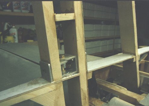
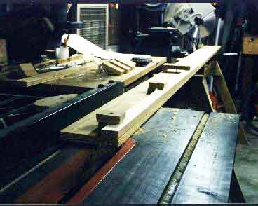
Spars were ripped to dimension and proper taper on the table saw, using a home made angle cutting fixture . The spars were inserted in their respective holes in the ribs and loosely clamped into place.
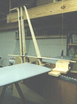
In order to ensure alignment of the tail to the fuselage, I used a reference line and two plumb bobs. The reference line is a long piece of fishing line pulled between two screw eyes protruding from the ceiling. The line is longer than the plane both forward and aft. A plumb bob is dangled over the centerline of the firewall, and the plane set directly underneath. Then the other plumb bob is used at the tail to locate the fuselage centerline at the aft end of the plane directly below the reference centerline. The fuselage must also be level across the main spar or longerons, whichever you're using as a reference.
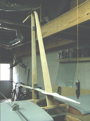
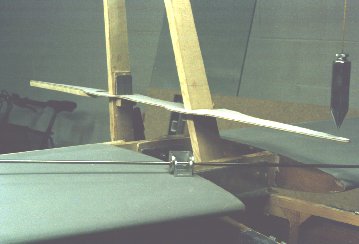
With the fuselage aligned with the reference line above, the spars were tweaked into alignment. This was done by using a plumb bob on each end of each template, pointing directly at the template/rib centerlines below. This not only ensured that the v.s. was aligned with the centerline of the fuselage, but that it was vertical as well. It might be worth mentioning that I discovered that my tailpost (installed during boat creation) was not perfectly vertical. There's not much way to install it vertical either, since you're at the mercy of bending forces from each of the two sides. The thought of ripping it out and replacing it was not very enticing, so I used one of the left over tapered "shim" looking things (that you get when sawing your h.s. and v.s. spars) epoxied to the side of the tailpost to shift the vertical centerline over, and belt sanded the other side. So now my tailpost has a built-in split. But since T-88 is stronger than wood, and there are .125" aluminum backup plates or hinges under each bolt, I'm not concerned, and neither is my DAR.
I also used a third rib/template identical to the larger one, which was screwed to the bottom of the fuselage and projected rearward to define the bottom of the rudder. The three hinges were aligned with a 4' 4130 rod.
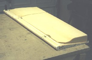
With everthing aligned, gussets and hinges were epoxied in place, and the forward spar was epoxied to the h.s. bulkhead. See how the humps are necessary to hold it all together and in alignment? After curing, the structural 3/8" spruce ribs were epoxied to the template/ribs at the 5" above the longeron and rudder bottom locations.
Also, two more 5/8" blocks were epoxied between the aft v.s. spar and rudder spar to hold the rudder on after the template/rib humps were sanded away. These can be permanent rudder leading edge sanding templates, as long as they are installed where they don't interfere with hinge bolt installation. The humps must be removed before sanding the foam by carfully sanding the ribs to the plotted airfoil template outline. Since the foam sands so much easier than the plywood ribs, a high spot would result if the foam were in place while the humps were sanded away.
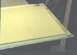
The structural skeleton was now ready for foam installation. 2" urethane foam was microed in place between the ribs and spars. Also, the hinge gap was filled with foam to create a gap seal. This foam was epoxied only to the aft v.s. spar. The rudder foam was installed such that one of the flat sides almost coincided with the left edge of the rudder ribs, so that sanding required on that side would be minimum. This was because the foam positioning is still a little fragile when only micro is holding it in place. I wanted to get the skin in place on one side with as little movement as possible.
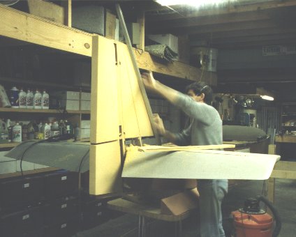
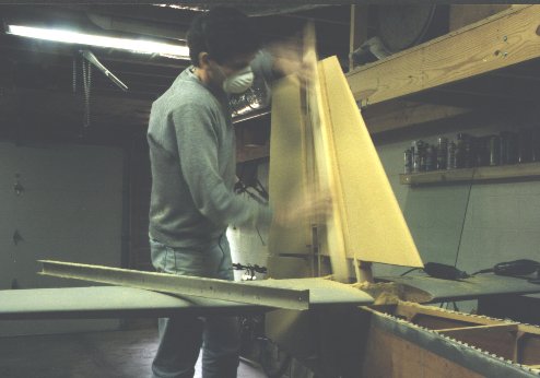
The v.s. and left side of the rudder were sanded to contour using the template/ribs as the guides. I used vertical strokes with a 4' pine 1x4 with self adhesive 25 grit floor sanding paper stuck to one side. Once final contour was within grasp, I switched to finer 50 grit sandpaper on a piece of 2x4 aluminum channel, and used horizontal strokes to eliminate any grooves in the airfoil. The result of sanding the vertical stabilizer and the rudder simultaneously was a perfect airfoil, top to bottom. The bottom of the rudder becomes a continuation of the fuselage, tapered to a point.
Once the foam was sanded to contour (the entire v.s., but only the left side of the rudder), the rudder was removed by cutting the two 5/8" spruce suppport blocks with a hand saw. With the rudder removed, it was now time to install the bolts to secure the hinges, which were already epoxied in place to maintain alignment.
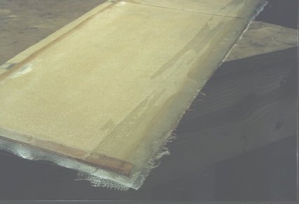
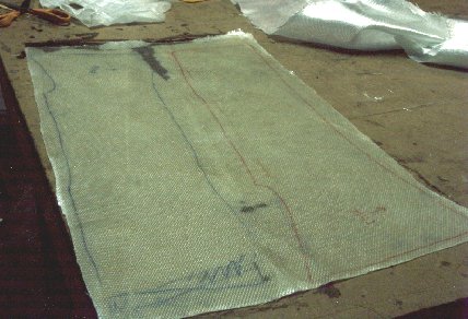
Both sides of the stabilizer were glassed at the same time. Paper patterns were made of the stabilizer so that each piece of fiberglass would be properly sized. These patterns included a few inches of wrap around the leading edge for extra strength in this critical area.
The patterns were laid on the table first, with a layer of 4 mil polyethylene plastic on top of them. On the plastic I laid out a layer of silk weave 1.5 oz/yd fiberglass "deck cloth", which would serve as my outer layer of skin, followed by a layer of 5.85 oz/yd fiberglass. Fiber weave was straightened and oriented perpendicular to each other (at 45 degrees from vertical and horizontal), before wetting out. The two layers were wetted out simultaneously. When all was wet, and the excess epoxy removed (I don't usually have to remove any, just squeegee it around to where it belongs), I could see the paper template showing through the plastic and translucent fiberglass. It was now a simple matter to cut the glass/plastic sandwich to size with scissors. I now had a fiberglass skin with exactly the right shape, bidirectional fabric weave oriented properly, and excess epoxy already removed.
Next I squeegeed a layer of runny (1:1) micro into the vertical stabilizer's foam, filling gaps between foam and wood as I went. I covered the whole stabilizer, then applied the left side fiberglass skin, squeegeeing the foam into intimate contact with the foam, and removing what few air bubbles I encountered. Next was wetting out the right skin fabric, which was already patterned and cut slightly oversize, since the micro starts to gel after 50 minutes or an hour.
You could easily cover the whole vertical stab with one continuous piece of skin, but you'd still have to apply a 2" or 3" fiberglass tape underneath on the leading edge to strengthen it up. But there's no reason that it couldn't be done that way, especially if time was limited due to high temperatures or something similar.
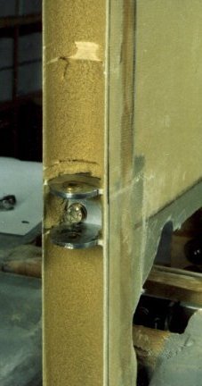
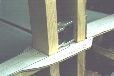
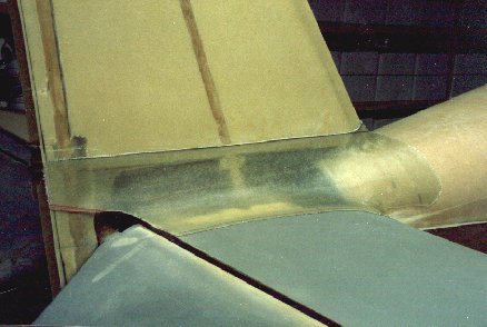
Next job was the hinge gap seal. Several pieces of small diameter PVC pipe wrapped with sand paper were used to hollow out the hinge gap seals to provide clearance for the rudder's leading edge. The sharp foam edges were then removed (leaving the outer skin in place) and replaced with flox. A 9 oz fiberglass tape was then installed to close the seal.
The resulting hinge gap seal.
Now it was time to deal with the rudder. Since the hinge gap seals were stuck only to the aft v.s. spar, a leading edge would have to be added to the rudder. Sanding guide blocks were epoxied in place to provide a template to sand to contour. This was also the time to install the hinge bolts thru the hinges, which were already epoxied in place. Foam was microed between the hinges and blocks and sanded to contour, using the template blocks as a sanding guide.
The left side of the rudder was glassed using the same method as the v.s., but an extra 3" wide 9 oz. fiberglass tape was run along the trailing edge before application of the rest of the skin. This adds considerably to the trailing edge stiffness. Once the left side was glassed, the right side could be sanded vigorously without consequence. When installing the foam, make sure that any micro squeezed out of the joint is wiped away. Cured micro blobs will make sanding the foam to contour very difficult, and will result in the aforementioned high spots. I removed my micro blobs with a dremel tool, but eliminating them before curing is far preferable.
Once sanded to contour, the last inch of trailing edge foam was removed from the right side to be replaced by flox to further stiff the edge.
Flox was applied, then a 3" 9 oz. fiberglass tape, followed by the usual skin.
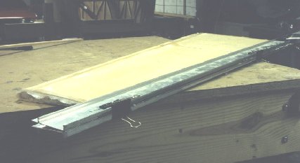
The trailing edge was then clamped between two aluminum angles (covered with duct tape as a release agent) to ensure a straight trailing edge. After curing, the trailing edge was sanded off square to a thickness of about 3/32". This edge is now strong enough to chop wood! Flutter should not be a problem.
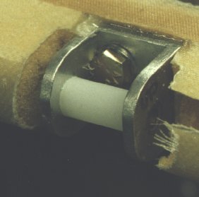
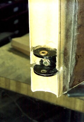
Because I'm using oilite bushings as my hinge bearings, nylon spacers were added between the bushings to prevent them from falling out.
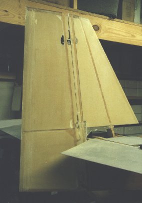
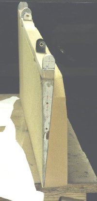
The resulting vertical stabilizer/rudder works quite well. The jig/template/rib method yielded a perfectly continuous airfoil which will certainly help to lower drag, as well as make the rudder and vertical stabilizer more efficient and effective.
Now that the horizontal stabilizer was now in place, a fillet could be constructed between the horizontal and vertical stabilzers. I temporarily installed the aft deck, and covered all nearby surfaces with duct tape to prevent damage.
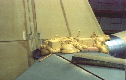
Urethane foam blocks were wedged under the vertical and between the horizontals, with two part expanding foam used to fill the cracks. Don't let this stuff run down inside your fuselage!
The joint was sanded to a concave contour with a piece of 4" PVC pipe with a piece of 36 grit self adhesive floor sander paper stuck to it.
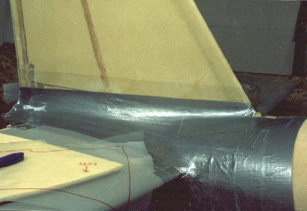
The foam was covered with duct tape as a release agent.
The glass was laid up in my usual fashion: by first making a paper template of the area to be covered, cutting plastic to match, and laying up a layer of 1.5 oz deck cloth followed by 5.85 oz cloth.
Cloth installed and curing.
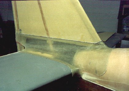
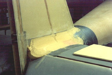
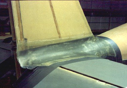
After curing, this fiberglass fairing popped right off, and fit perfectly.
The almost final result. Next, a joint was created under the surface, and forward part was glassed to the aft deck, while the aft parts became removable inspection panels. The panels have sufficient flex to allow the horizontal stab to be adjusted. A 3/32" vertical ajustment is good for about .72 degrees of incidence.
Return to Mark Langford's KR2S Project