Corvair Valve Train Geometry
Corvair Valve Train Geometry
My first clue that my rocker geometry wasn't right was when I ran out of adjustment on the first valve that I tried to adjust after adding .020" of cylinder shim to decrease my compression ratio to 8.4:1. It's something I've always been a stickler for when setting up high performance solid-lifter VW engines, but as soon as I started thinking about the hydraulic lifters on the Vair, I wondered how in the world to set it up correctly, since the lifter would simply compress. Ray Sedman gave me a pretty good description over the web, and Tom Cummins clued me in to what was included in Clarks' "Valve Train Geometry Kit".
It consists of two adjustable pushrods, and two solid lifters, which solved my problem of how to deal with hydraulic lifters! Although I already had an adjustbable pushrod that I made for VW usage, I needed the solid lifters to do this job, so I ordered their $40 kit immediately.
Actual determination of correct pushrod length requires removing the pushrod tubes, which I did by loosening all of the head nuts down to about 5 ft-lbs, then removed the pushrod guide plates for the one cylinder that I was checking, and then the pushrod tubes for that cylinder, replacing and lightly retorquing the guide tube plates after the tubes were out.
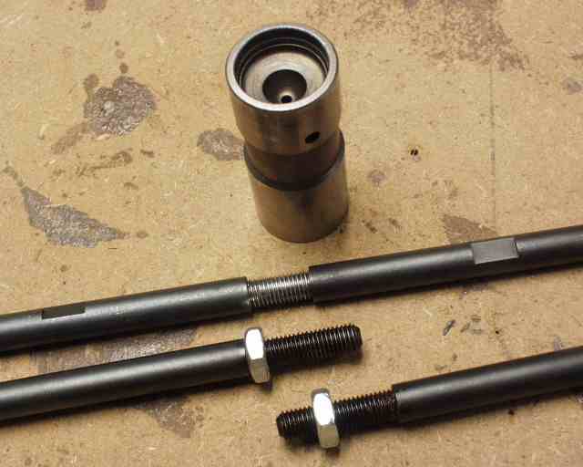
The only thing was that the adjustable pushrods that Clark's sells had about two threads left from unscrewing when my valve geometry was correct, so I cut the head off of an AN4-16A aircraft bolt and threaded it all the way with 1/4-28 threads, then used the two "female" halves of their two pushrods to make one very stout pushrod, with another 3/8 inch of adjustment (top one). This setup is way stronger than the Clark's setup when you are at the high end of the length spectrum, and allows you to delete the jam nut, which enables you to slide the whole works through the pushrod guide plate without disassembling the pushrod or removing the guide plate.
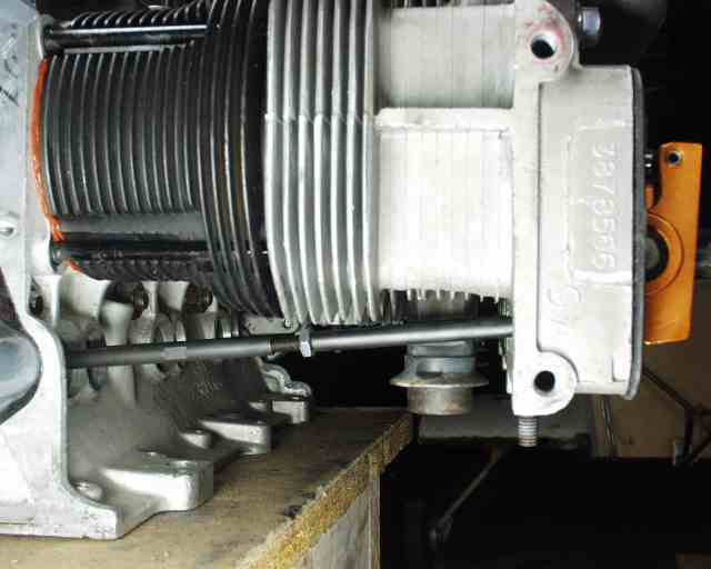
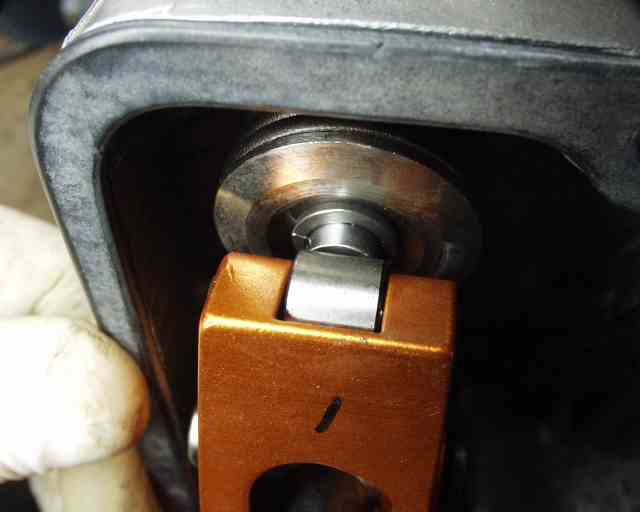
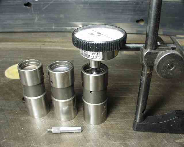
Basically, you replace the hydraulic lifters with the solid ones for whichever cylinder you're checking. Rotate the engine around until that cylinder is ready to fire at top dead center on the power stroke (if you look at the cam from the top cover, you'll see that both cam lobes are pointed toward the side opposite to the "active" cylinder. Install the rocker arm and loosely install the rocker nut. Then rotate the rocker (as if the pushrod was pushing on it) until the roller contacts the valve a little higher than it does in this photo, slightly below the centerline. Then take out the slack in the pushrod to tighten it up to zero clearance, while wiggling the pushrod to make sure it's seated properly on both ends. Then tighten the adjusting nut finger tight to remove all freeplay.
Rotate the engine until that particular valve is fully depressed (it'll start to come back up, so stop and back up to the approximate bottom point). If it looks as high up from the centerline as it started out BELOW the centerline, you've got it right! You want the roller travel to be equadistant from the centerline from the no-lift to the full-lift condition. These two pictures show that the contact area is still biased a little toward the bottom of the valve face, so I'll need the pushrod to be slightly longer than it is now.
Since I haven't shown you a roller rocker yet, here's your chance to see one. Since the roller can't possibly exert a side load onto the valve (unlike the stockers), valve guide life is improved substantially. I wrote an "I" on this one, since the exhausts and intakes are at different angles and require a different rocker shape. And since these are solid, and have bearings at the pivot point and valve contact points, maximum lift is achieved. The stock rocker "slides around" while depressing the valve, and doesn't even follow the same path every time, so its action is a little "iffy".
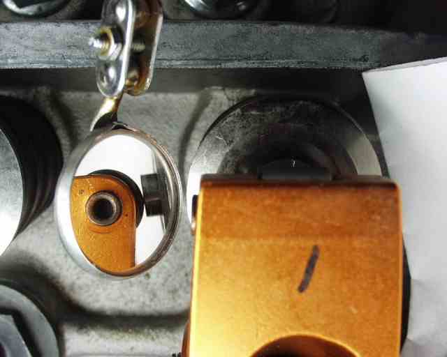
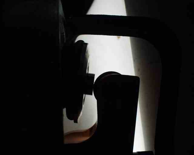
I eventually developed the method of using a mirror to get a good view of the roller's contact area. This is just about where you want to see it at the no-lift point. It will move up as the cam pushes the pushrod out, or as pushrod length grows.
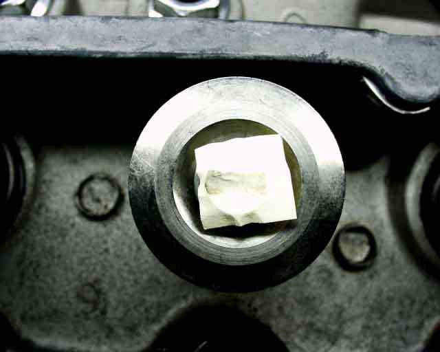
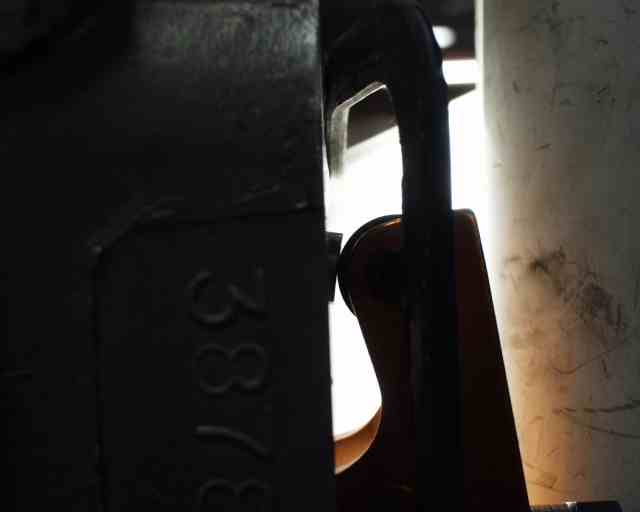
This picture is a little overexposed, but you can make out the contact area right in the middle of the valve. This is a small piece of a Post-It note stuck to the valve head, and the lightly oiled roller has mapped out its track across the valve face from zero-lift to full-lift.
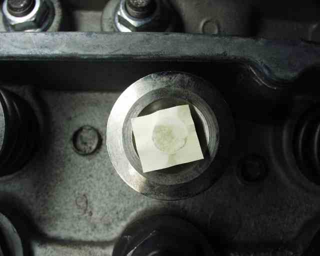
Here's what happened when I put in the stock pushrod, and used the stock rocker/ball combination. You can see that the contact area is larger, but still off-center. For the roller rockers, the distance that the rocker traverses across the face is pretty small, since the line of force is merely a line, which makes it pretty easy to see exactly when it's centered. For the stock rockers, the face of the rocker is closer to flat, which covers more of the valve face.
The instructions that come with the kit say that the solid lifter is about .090" shorter than the usual hydraulic lifter, but I just had to measure it to make sure (you know me), and it was actually .126" shorter! The instructions say to insert a 5/16" ball bearing in the end of the lifter to make measuring easier, and they weren't kidding! It sure makes the measurement easy and repeatable. Fortunately, I was only interested in the DIFFERENCE between the two lifter "heights", rather than the overall height. My average of all pushrod lengths ended up being right at 10.50", and since the stocker is 10.26, and after you subtract the .126" lifter shortfall, and add an extra .0125" for the quarter turn difference between their half turn preload and WW's 3/4 turn preload, I arrived at a pushrod length of .139" longer than stock. This is partly due to increased cylinder shim thickness (.062") and different valve heights (swirl polished from Corvair Underground), and the roller rockers themselves. Ray Sedman of American Pi fame is making me a set of those next week. Best I can tell, he knows more about Corvair performance than anybody else on the planet!
The bottom line is that if you throw your engine together with non-stock valves, different cam, different rockers, and different thickness cylinder shims and head gaskets, your pushrods are probably not going to be the right length. Mine, with stock-length pushrods, were barely on the edge of the valve stem face. Side loads would have been high, valve guide wear would also have been high, and some small fraction of power would have been lost to friction. Even if you're just changing cam and valves, and buying new rockers and balls, your geometry is going to change. The procedure above works just the same with the stock rockers. The least you can do is take a look at it while you're assembling your engine. And even if your engine is assembled and running, you can check it...
Return to Mark Langford's KR2S Corvair engine