Mark Langford's KR2S Project
KR2S Corvair Oil System
created Sept 26, 2004, updated Sept 2010 with oil cooler testing
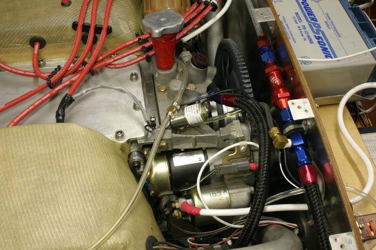
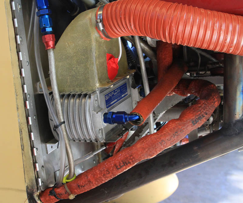
Here's a shot of how the oil system looked shortly before ready to fly. Please ignore the temporary plastic primer lines and other no-no's like lack of fire sleeving in this photo, as much of this stuff changed before first flight, and continued to evolve as the hours mounted. If you look where the stock oil filter used to be, you can see a blue AN-6 fitting connected to an Earl's "Pro-lite" hose. I bandsawed the filter mount off and used the one closest to the fuel pump as the oil outlet from the engine, and welded the other one up (although you could use it as an oil return). The port that feeds this hose used to run to the filter (from the oil pump), but now runs to the filter and cooler, and includes a thermostatic bypass on the way to the cooler. The return from all of that stuff re-enters the case via what was formerly the oil cooler return port. A lot of this stuff ended up underneath the engine rather than on top, mainly in order to reduce the heat soak opportunities for the fuel lines.
This retains the filter bypass, and adds thermostatic control sandwiched between adapter and filter for more rapid engine warming from a cold start. These inlet and outlet passages are connected inside the case, but I had to do my homework and trace the system to prove to myself that it would work. One of the oil cooler ports is now blocked off, using only the lower port that returns oil to the case. You can barely see the blue fitting hiding to the left of the starter, down below the square NPT plug. This oil system is now officially "flight tested", as I have 75 hours on it at this point.
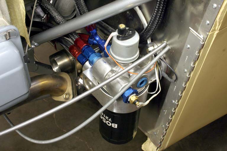
Here you can see the 502ERL sandwich thermostat, purchased from Earl's.
I welded an aluminum boss the top of the remote oil filter mount (Earl's part number 2277), which I tapped for the VDO oil pressure sensor. The adapter features inlets and outlets on each side, so there's a lot of versatility here. I used one of the extras to mount a temperature sensor for the EIS system, but I need to replace the spade terminal with a screw-type connector. I placed this stuff down low so changing the oil filter will not be a mess-making affair.
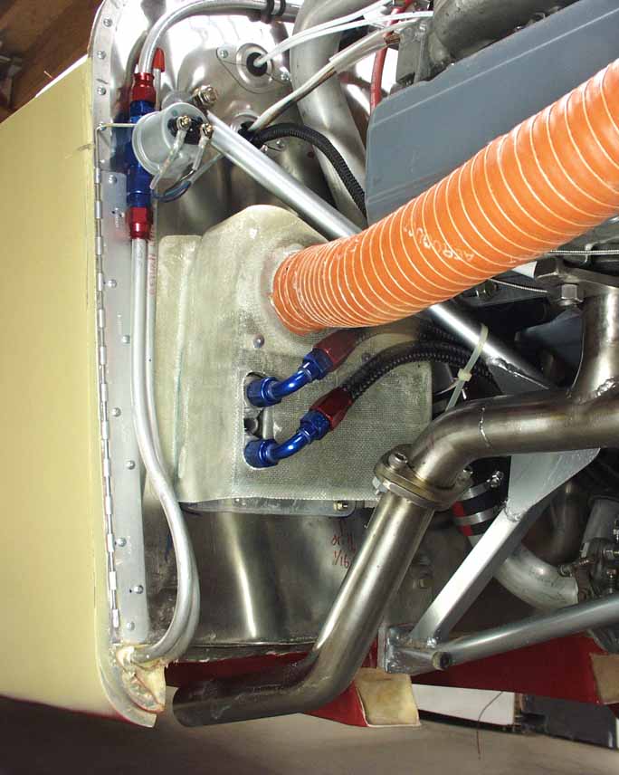
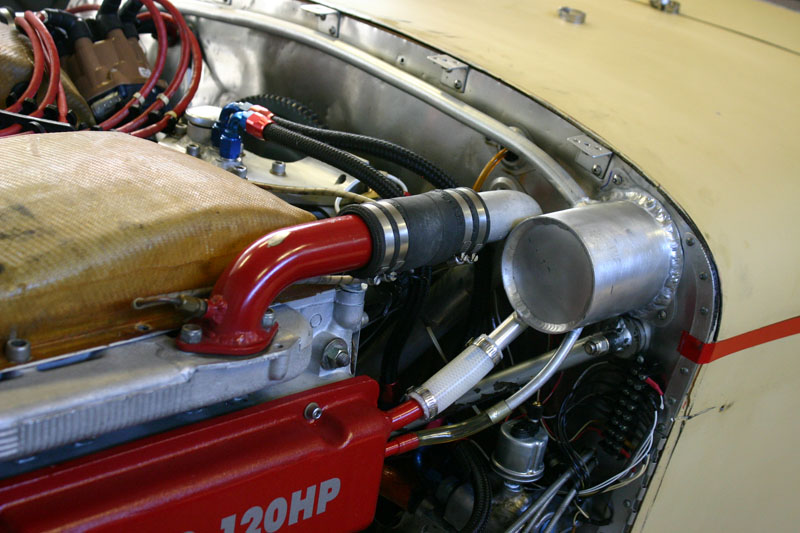
This is the stock Corvair folded fin oil cooler with a home-brewed fiberglass shroud on top, fed by a 1.5" SCAT line connected to a hole in cowling, just below the air inlet. This worked OK most of the time, but in a long climb to 11,500' on a hot day, it was not uncommon to hit 260F! Running the Airventure Cup race in 2010 (with 900 hours on the plane) was my incentive to improve the oil cooling system, since I was going to have to run wide open for 3 hours straight. I "instrumented" the cooler ducts with a differential pressure gauge, which was inside the cockpit, with two 3/16" inside diameter urethanae lines running out through the carb heat inlet and into the engine compartment. I made two "probes" that were nothing more than 3/16" aluminum tubing with holes drilled crossways through the tubing, similar to a static probe. Then I inserted on into the the oil cooler shroud and the other was positioned below the cooler, near the cowling outlet. I was surprised to find a relatively small pressure difference, only 1.5" of water at 160 mph straight and level speeds. That's practically no flow through the cooler, despite having 160 mph air coming in the front. This requires further investigation, obviously.
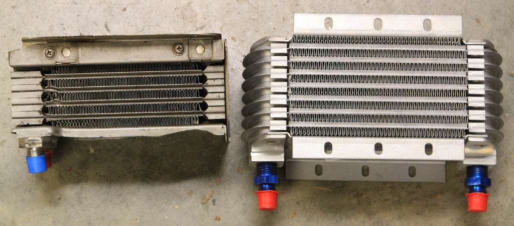
Although it was clear that I needed better airflow, I felt like a larger cooler wouldn't hurt either. On the right is the new oil cooler from Airflow Systems. It's also a "folded fin" cooler design similar to other aircraft oil coolers, but has at about 75% more area than the Corvair cooler (on the left). Otherwise the construction is very similar. The Airflow has a convenient flange on top and bottom to fasten ductwork to. Another big advantage over the stock Corvair is this thing is new, so there's no trash in it, and it's new, rather than "ragged" like the folded fin Corvair on the left.
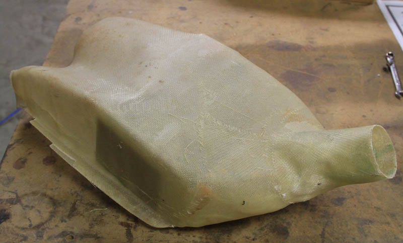
So I started by making a new inlet duct to use the existing 1.5" SCAT line and interfacing with the new cooler.
I ran the differential pressure test again and picked up .5" of water (total of 2") at 160 mph, so the duct design and tigher fitting of the flange helped get more air through the new cooler. Temperatures seemed to drop by about 22F degrees at the high end, which is far less than I'd expected. Of course given the fact that there's practically no airflow, that's not surprising at all!
By the way, there's an example of how NOT to install fire sleeve on the line coming off the cooler...it should have a wrap on the end to tighten up and close out the end of the sleeve. Otherwise the insulation will get soaked with oil and become a fire hazard!
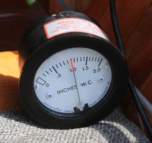
Here's the 2" "Minihelic" differential pressure gauge at work, at 100 mph. I also checked the pressure difference between the static system (same one that's proven accurate via my pitot system) and the area directly beneath the cooler, and about the best I can get out of that is a negative 3" of water at 160 mph, and less the slower I'm flying. That's not a great amount of suction, so I need to improve on that situation somehow. One option suggested by Bill Genevro at Airflow Systems was the installation of louvers in that area to create a local low pressure area. I may do that.
That set of louvers might be ported directly to the bottom of the cooler via the previously mentioned flange, and I may try something like the duct above, which I built back in 2006. One problem with this one is interference with the exhaust pipe, and by the time you dodge that, the effective outlet area is pretty cramped. It was also intended to receive air from the back of the passenger side plenum, but the alternator ended up obscuring access to the extent that I couldn't get air from there. As a part of my 2010 oil cooler improvements, I may build a new lower duct to bolt onto the bottom of the Airflow cooler and see how much effect that has. I've tested the pressure at the bottom of the cooler (which is only about 4" above the bottom of the firewall) and the cowling outlet duct 4" away, and there was practically no difference in the pressure levels, so I don't think that'll help much. The exit itself must be modified to get lower pressure in that area, and I'm not real wild about a drag-inducing lip on the bottom of the cowling. That would be the no-brainer though, and I may do that just to quantify the difference, as well as the impact to overall aircraft speed.
October 2010 - I've finally arrived at an oil/vapor separator that works! Although the previous home-brewed separators that I fabricated and located at or near the stock fuel pump mount worked to some extent (some better than others), it's difficult to avoid the oil being slung up from the crankshaft directly below at high RPMs. Since I have Total Seal rings and 80/80 compression on all six cylinders, I don't have a lot of blowby, but there's always going to be some combustion blowby. And it has to have some way to escape to keep from pressuring the case and seals, which could lead to excessive leakage at the main and pulley seals, for example.
The valve cover location of the tubes is stolen directly from William Wynne, and although the separator itself looks like a knockoff of the inexpensive separator sold by Wicks and Aircraft Spruce, I arrived at this shape "in a vacuum", believe it or not. Knowing that I needed the largest "condensation volume" possible to ensure sucessful operation, the predecessor to this one was a 12" long 3" diameter aluminum tube fastened across the top of the firewall. The reason I don't have a picture of that installation is because when I went to install it before leaving for the KR Gathering, it wouldn't even fit!
So it became obvious that I'd have to settle for less, so I lopped a bunch of it off and came up with this one. It fits nicely where it is, and only after admiring the genius of it did I realize that it's very similar to the one they sell for $55! That would have been a lot cheaper than my labor to make this one, although I'm not sure the larger unit would have fit where I shoehorned this one.
Some folks have asked me "how does the oil vapor know to go up the big tube and return as a liquid through the small tube?". I'm not sure that it does! The flow through both may be exiting the valve cover during high speed operation, but what matters is that there's enough tubular cross section on the 5/8" line exiting the can to only allow vapor out without entraining liquid with it. The large line going into the bottom extends about halfway into the can and is directly at the aluminum wall, so the theory is that vapor is cooled there and condenses out to drip down to the bottom. Since only a few drops of oil are condensed out each flight, it may sit in the bottom of the can until the plane is parked, and then it'll run down the 3/8" tube and back into the valve cover. In the photo you may notice that there's a clear urethane tube on the lower side with a dip in the bottom. That's so I can see what is collected, and will be able to assess water content in the condensed liquid.
There were some more improvements to the oil system in 2007 with the 3100cc engine. It's still evolving in 2010. There was another round of improvements in 2008 on the front bearing 3100cc engine.
Return to Mark Langford's KR2S