Mark Langford's KR2S Corvair Engine Mount
Corvair KR2S Engine Mount
revised December 1, 2001
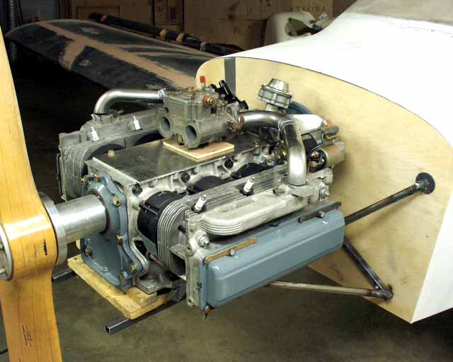
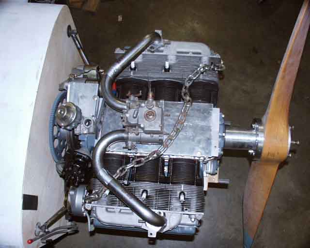
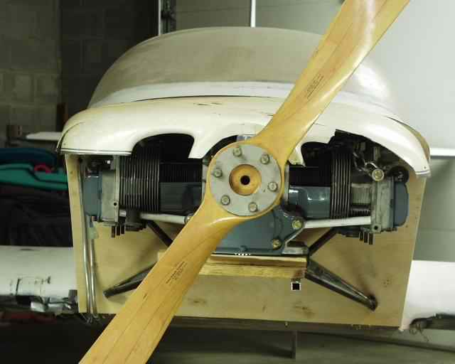
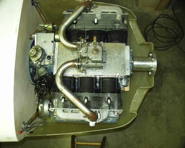
Now we're cookin'! Here's the engine on a temporary "practice" mount that I welded up out of mild steel tubing, mostly as a design/balance study, not to mention the welding practice. I'm fairly convinced that the engine is going to weigh right at 250 pounds "all up" with everything needed to run except a battery and fuel. It's not nearly as pretty as Pat's, but I'll bet mine has a little more power!
I was originally going to put my Weber 40DCOE carburetor on top, but would have been forced to have a 2" tall blister up there. Also, the air on the bottom of the cowling is higher pressure, and I had loads of room down there, so I later decided to move it down below.
The engine's closest point is the starter, which is about 3/4" from the firewall. There's still plenty of room for oil cooler, filter, coil, etc., and lots of room for the exhaust system. The intake system isn't welded up yet. Still waiting on the laser cutter to cut the flanges out for me.
This is a 58" diameter prop that Doug Steen let me borrow. It probably has way too much pitch (74"), but will make a good test prop. With a level attitude, I have 7" of prop clearance with the ground. I'll probably end up with a 56" prop, yielding 8" clearance. My thrust line is 2.5" below the top of the longerons. If all else fails, I have some 2.5" gear leg bracket extensions I'm working on.
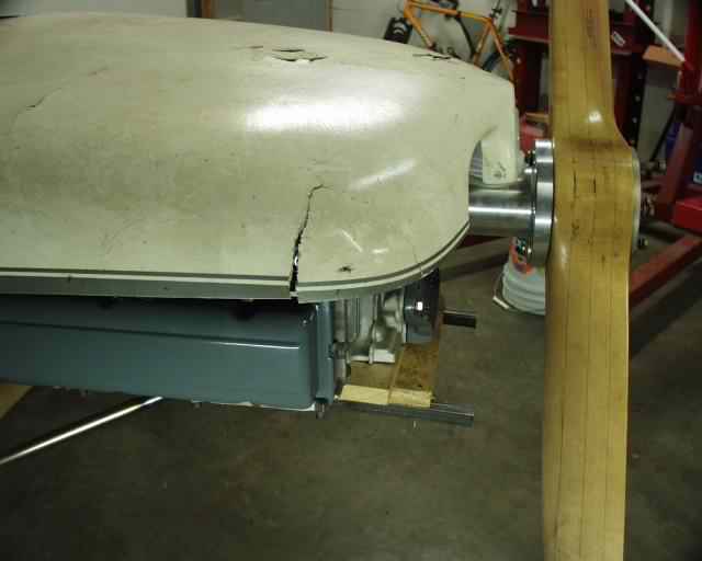
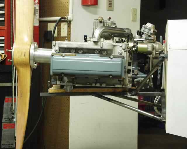
This cowling is a stock early KR2, which is about 4 inches shorter than a Revmaster. This one is positioned just about right, but a Revmaster would point in from outside to prop spinner, filling in this gap.
The closest that the cowling gets to the valve covers is about 2.5". The intake manifolds are actually holding the cowling up, so they are a perfect fit. Other than the Weber carb, nothing else interferes with the cowling.
Jim Hill donated this cowling to me when he cracked up his KR2 in a cotton field a few years back. I really wish I'd let Kenny Boyer give me that Revmaster cowling that he made for me and brought to the Gathering. I thought at the time that I'd have to make my own, but it's now apparent that it would have fit with room to spare!
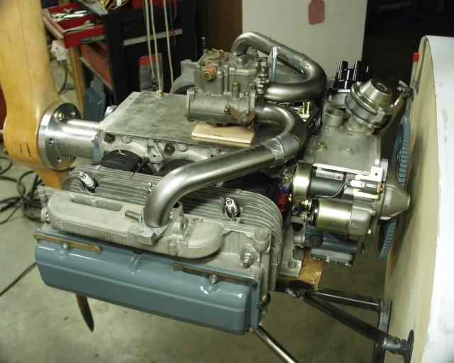
With the engine thus mounted, I was able to do a preliminary weight and balance. With the wings installed and airplane leveled, the pilot's side was 304.5 pounds, passenger's was 307.5, tailwheel was 16.5. I used "stand-in" weights for much of what's missing, but will add a 15 pound exhaust system to the front, counteracted by 8 pounds of aileron counterweights and maybe 3 pounds of rudder counterbalance. My battery is mounted to the rear of the firewall, and could easily be moved rearward (like in front of the spar) but I don't think that'll be necessary at all. Any other weight gains (like paint and wingtips) will probably be close to the CG, so I think all is well. Grand total is now 628.5, so I'm confident that I'll still be under 700 pounds. That sounds like a real porker, until you consider that I expect at least 135 hp at 3500 rpm.
The pictures above were taken without all of the "standin" stuff piled on top of the engine, like spark plug wires, oil cooler, filter, etc. The chain represents the cowling. I think I could have built to this point and only had it weigh 600 pounds, if I could do it over again.
Most of that weight I'm referring to is stupid things that I did while building mine. For example, I was originally going to use the NLF(1)0015, so my spars were not as tall, so to get the same strength I made my spar caps 5/16" thicker. Then when the new airfoil came along, it was back to stock height, so I had to add another quarter inch back to both top and bottom to get back to the original depth. I figure this cost me about 8 pounds altogether. Then I had epoxied the wing templates for the NLF to inner and outer edges of the stub wings, and they had become part of the wing tanks, so I couldn't cut those out, so I cut out some more (with lightening holes) and added them on to the others. More weight. My aft deck has too much foam in it, up to 2" in places. The first one I built was super stiff and only weighed 6 pounds. I should have perfected that method (vacuum bagging) and done the next one that way, but it was a lot easier to just hog out a huge block of foam and glass both sides. This is where I got the idea to do wing skins the way I did them though. The final one weighs about 11 pounds, and it could easily have been 5 if done correctly. The canopy frame used lots of glass to stiffen it. I should have used carbon fiber for the whole frame and it would have been a lot lighter. If I had planned my aileron cable routing better, I'd have simply run an aluminum conduit through the wing tanks, rather than partioning off a wedge shaped area for "future expansion". That would've saved 2 or 3 pounds, and given me 3 or 4 more gallons of fuel capacity. The Cleveland brakes are pretty heavy, so I'd be tempted to use the GPASC or Tracy Obrien's wheels and brakes. I'd also have used the 18/15% airfoil to lighten up the spars and increase fuel tank volume, but I'd have had to add 2" to my spar caps to use it!
In the "other than weight" area, I'd use bent up center spars so the flaps could start at the wing root, spring bar gear fastened to the spar under the fuselage sides (like Grove Aircraft sells) but 6" taller than the Diehl gear, and I'll eventually try elevator balances like Richard Mole designed (the ones on Dana's tail) which Richard says will improve stability and while balancing the elevator (although my intuition makes me wonder about the stability part). I'd also make the fuselage a bay longer and the tail only 76" wide, and a gullwing canopy like Troy/Bobby's (but made from a Dragonfly canopy. And I'd widen the fuselage 6" rather than 4" like I did. I'd also put a 1 or 2 gallon header tank in the front deck that stayed full, kinda like Don Reids's. I may still do that one.
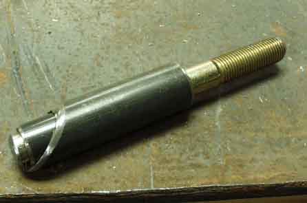
Originally, I had planned to mount the engine mount "tray" directly to the firewall. These bolts were to protrude through the firewall and pick up a pair of 4130 tubes connecting the top and bottom horizontal spruce members.
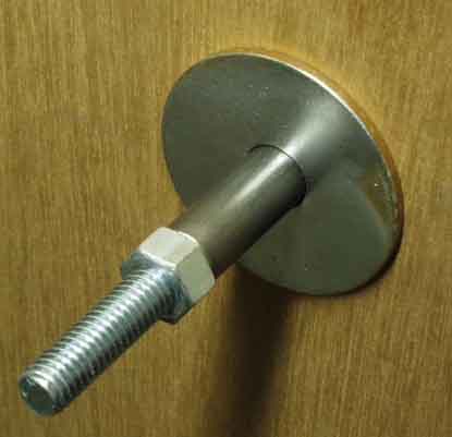
The "spools" were made out of 4130 tubing and AN970 washers. Here they are jigged up on the firewall, except that the firewall has a piece of quarter inch plywood between the mount and the acutual firewall, so I wouldn't burn the real thing while welding. Using threaded rod minimizes heat transfer area to the bolts, to minimize the possibility of charring the bolt holes while welding.
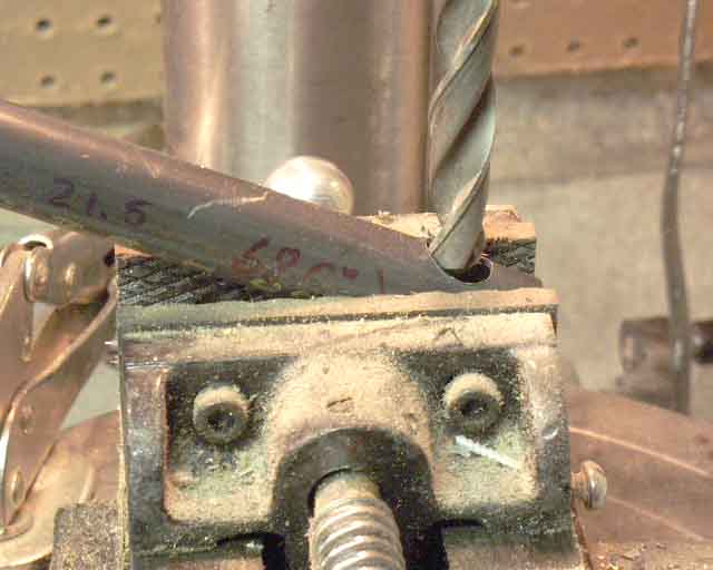
While I was almost forced to drill some holes in my firewall to determine some basic Corvair/KR2S measurements, now that I've done it, you don't have to. So the thing to do now is build the mount up on a jig (preferably made from half inch steel) using the measuremetns that I've come up with, and then simply locating the mount properly to the firewall and match drilling the holes.
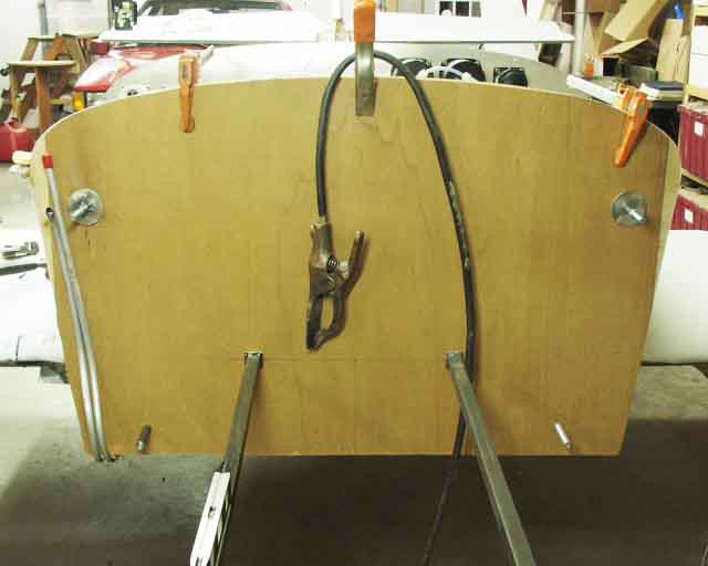
Here you see another reason why I mounted those bolts to the tray, so that I could jig up the mount on the airplane and ensure that the tray was level in all directions before any welding.
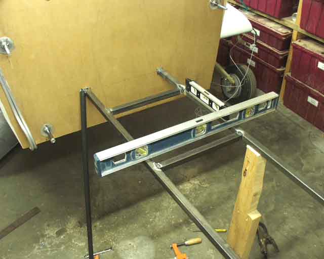
Here, everything is leveled and held in place while the diagonal braces are fitted.
The diagonal braces were drilled at an angle so that a perfect fit with the spools could be achieved.
This is what the Dragonfly guys are doing. One look at this (assuming it's been load tested and it works) convinced me that I could get away without the lower diagonals, which make dodging the exhaust system a little tricky. Note that this Dragonfly system is essentially like what I had planned, with the tray fastening directly to the firewall. But the difference here is that there are no supports below the tray, so all the loads are reacted at the top two diagonals, and at the firewall in the same plane as the tray. If his works, mine surely will! It should be noted that I've yet to lead test mine, but I will shortly.
This is William Wynne's motorized spool welding jig. He just sets the parts on there, tightens the nut, turns it on, and MIG welded the nut to the 4130 tube. While at the Corvair College, we pressed one of these just about inside out, and the weld didn't break, so I guess it's good enough!
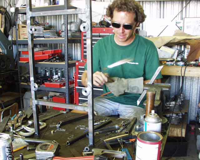
So I went to the Corvair College, after William assured us that anybody that wanted to learn how to weld 4130 steel would get some hands-on-experience. I welded several of the joints on this tray, with Terry Bailey and William's supervision. I figured I'd learned enough to go back and finish up my mount, which I left fastened to my airplane, since I didn't have time to completely tack it together and bring it with me. And if I made a big mess of it, it would be good experience for a second "keeper" mount. Well, this didn't sit well with William, who informed me that my attitude was unacceptable. I simply needed to build a mount (right now!), take it home, mount it to the air frame and be DONE with it! So I called my wife to take a few critical dimensions from the firewall, and we went to work. During dinner we finalized a new mount design on a napkin (having seen what the Dragonfly guys were getting away with). Sunday morning I went to work cutting and notching tubing, Pat Panzera welded up a bunch of spools with the MIG welder, and William fired up the torch to get this show on the road!
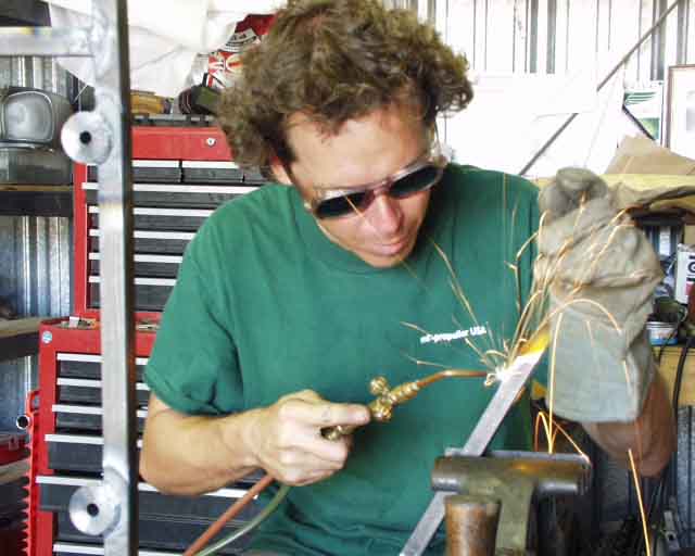
No, he's not wearing a leather welding apron, or long sleeves, but he definitely knows what he's doing.
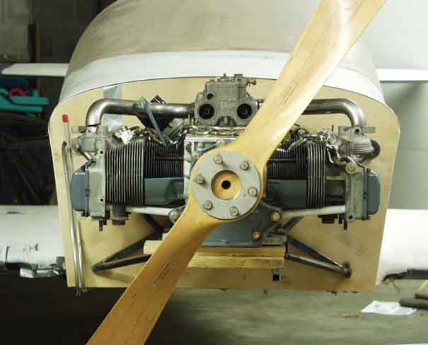
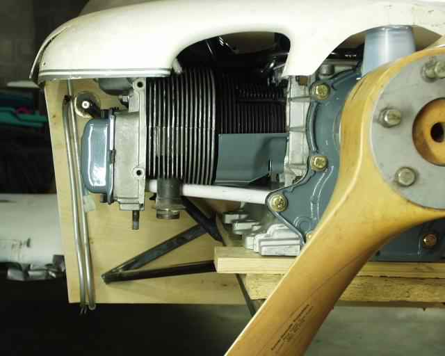
Here's what a Revmaster cowling looks like under a Corvair on a KR2S, with prop hub about 29.5" from the firewall (just like a stock KR2).
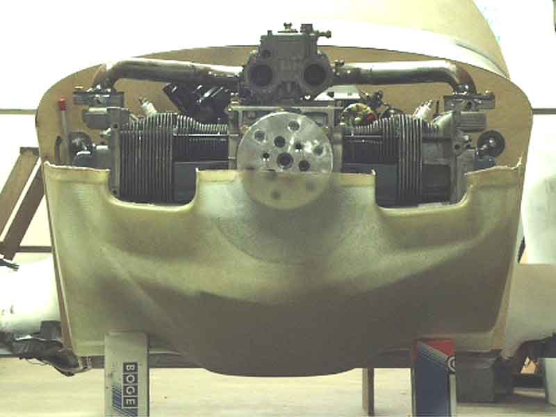
Obviously, the bottom of the mount is a little low in this shot, since I hadn't cut the forward extensions of the tray yet (which will become cowling mounts).
Here's why I let William let me talk HIM into doing the welding for my mount! Thanks a lot for the help!
Update, as of December 1, 2001
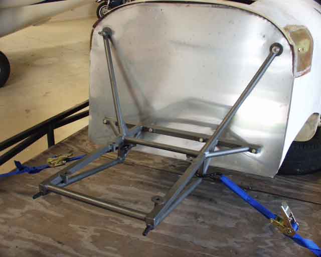
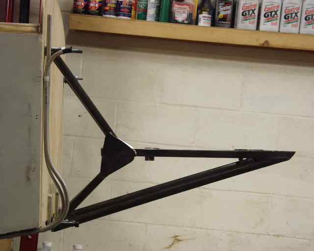
Here's the finished product. Please ignore the fact that the bottom of the mount misses the firewall compeletely! That's what happens when you try to recreate your firewall/engine geometry when you're 800 miles away from the airplane! This little mistake cost me about 2 more pounds to reinforce the "new" attachment perch.
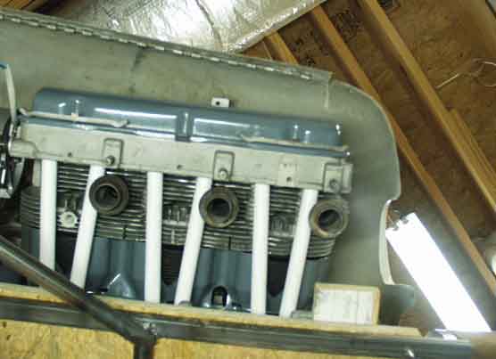
The bottom line is that if you mount your engine so that the bottom of the aluminum case is 7.5" up from the bottom of the stock KR2S firewall (which puts the thrust line up 13.875" from the bottom) you'll just barely miss the mechanical fuel pump if you use a Revmaster (or presumably stock KR2S) cowling. Other than that, I put the upper diagonals over close to the longerons, and centered on the 3.5" x .625" spruce cross members, backed up by .125" aluminum backing plates, and rested the bottom members on the lower edge of the firewall at the intersection of the two spruce cross members that are at a 101 degree angle to each other.
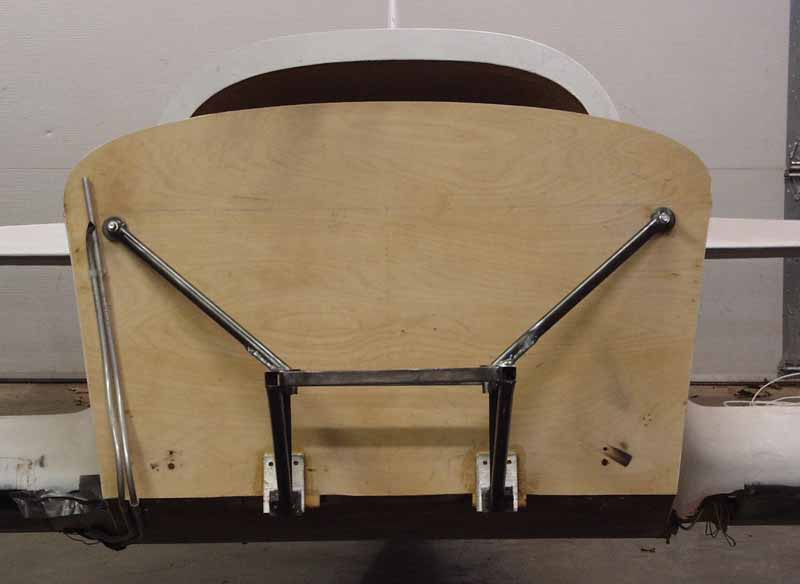
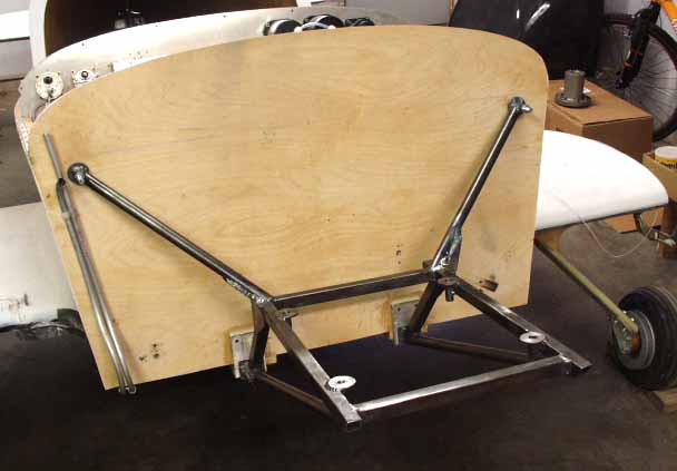
Somebody asked what the dimensions are for my mount. These pictures, along with a Corvair engine block, should answer those questions. Here's the front view. All tubing is .049" wall 3/4" diameter or square.
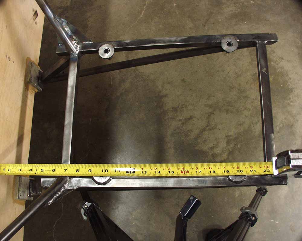
Top view. The end of the tape measure is touching the firewall. This results in 3/8" of clearance between the nose of my starter and the firewall.
Side view. The airplane wasn't level when I took this picture.
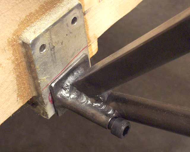
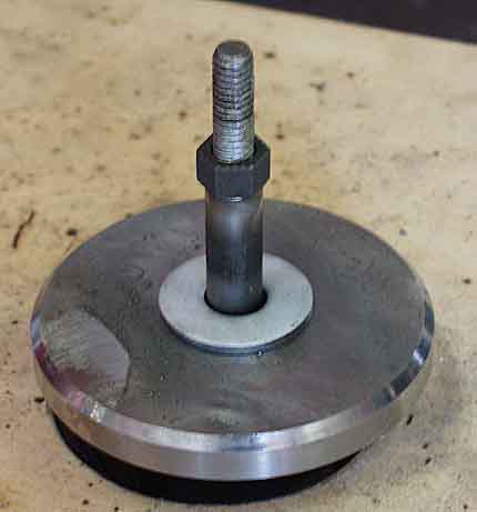
Lower mount detail. The tubing that the 3/8" bolt goes through is 1/2" o.d. .058 wall.
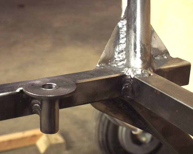
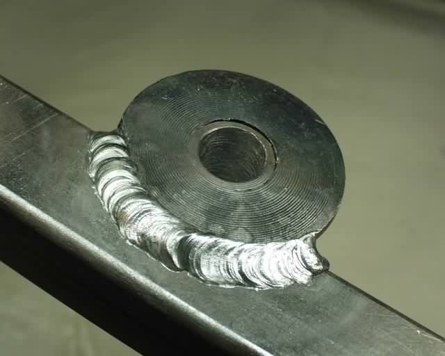
Joint details. Gusset is .063" thick 4130. The round things are just big washers.
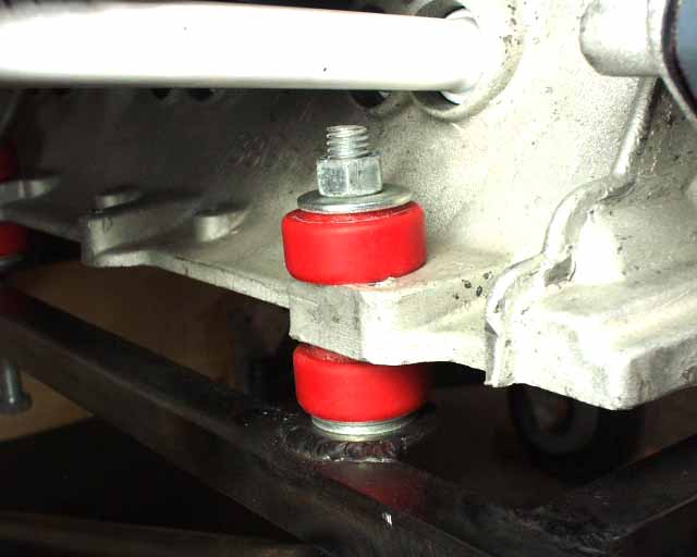
Urethane shock mount bushings are inexpensive and last forever. Obviously, hardware is temporary. Many of the details of this mount are borrowed from William's Piet design, but the geometry was a joint effort cooked up over dinner at the Corvair College. Note that it is untested at this point.
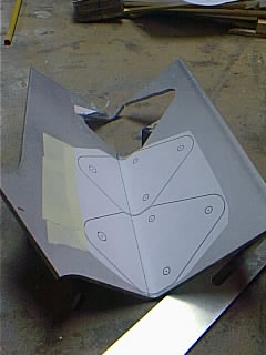
These are the reinforcements for the cabin side of the firewall, to tie the two spruce members together better. The plans called for two firewall reinforcements consisting of a large 1/8" aluminum angle that weighs 3.5 pounds for both top and bottom. My two little bent-up plates are all I need, and weigh less than 3 ounces for both. Since my engine mount points extend to locations near the longerons, there's no need to stiffen the firewall out in the middle. Hmm, that would be a total of 7 pounds saved. All I used at the top was some 2" square aluminum plates to keep the mount from pulling out. I also reinforced the corners with several layers of glass tape laid up over flox fillets to assure a perfect connection between memebers, in addition to the T-88 glue bond.
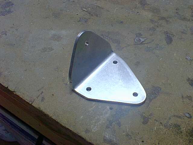
This lower mount reinforcement is a 1/8" thick piece of 6061-T6 bent at a 101 degree angle with a 3/8" radius, with a weight of 38 grams, in case you were wondering. It's located behind the firewall (cabin side) and serves as the connection point for the lower engine mount points.
Return to Mark Langford's CorvAircraft engine.